
-
I got it from an old scope circuit board. The board is most likely 45 years old. The assembly diagram states it's a UA741, but here is a picture of it too.
Last edited by Mark-VA; 06-18-2024, 09:05 PM. -
Have you tried determining the transmit frequencies on the 800?Originally posted by Altra View PostComment
-
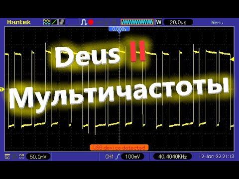
I may have but it's been 4 years, so I don't recall. Here are some photos of the Park and beach mode, One photo from the detector and the other from a micro that I programmed to analyze the timing. You can see in park a 2.5khz repeat cycle. You can find the frequencies in the manual, but I doubt they give a break down for each mode.
Park 1 mode
Beach mode
Comment
-
-
I can see them on my pc? On my ceii phone they were not visible earlier.
I think it would be more informative to scope the current and voltage at the same time. OverlaidComment
-
Look at this person's channel --- there are all the oscillograms for Deus. To translate into English, turn on subtitles.Comment
-
Hello
I am working on a Deus 2 clone project and I have an FMF coil at home and plan to open it up soon and examine the PCB which will tell us a lot about how this metal detector works.
Comment
-
My project is based on the STM32H7 processor and, unlike the XP Deus, does not have an external ADC but uses an internal 16bit ADC. Here are my final PCBs which still contain small errors. I am testing the project on the original coil X35 22cm, if anyone is interested in working together on this project, we can create a special contribution on this forum.Comment
-
I look at the diagram Current probe sch.pdf - maybe someoneOriginally posted by Altra View Post did not bother to review the pdf files of the TL072 and
NE5532. a closed current loop of thick copper wire and a step-up transformer?Comment
-
Care to elaborate pleaseComment
-
both types of op-amps need a load resistance greater than 600 ohms -NE5532 - , respectively 2 kilohms - TL072. choke in the picture from 06-14-2024, 07:58 PM #8 , wound on a toroid - the thick copper wire ( closed loop ) through the choke ...
...
Comment
-
Hi Riss, I think you are confused. This is a non contact, transformer-less oscilloscope probe. It's for relative visualization of the coil current. Carl posted the idea above, which I have never seen before. Maybe he can explain it. All I know is it works!Comment
-
Quote:".... the idea above, which I have never seen before."
The idea is you apply a short-circuit, or near short-circuit to the coil. Then the current flow is purely dependant on the inductor, in theory. In practice, the L has some series resistance, so this needs to be kept low. And in practice, you would need a low value physical resistor as a load, so you had something to measure the voltage across. If youkeep the load resistor low in value, the generated voltage will be small, which is not ideal.
The opamp-based current-to-voltage converter circuit provides a virtual short-circuit to ground, but because it has an independant feedback resistor of its own, it can have any gain ( current-to-voltage ) you like.Comment
-
Thanks Skippy. Years ago I owned an apparatus called a "Tone Ohm". It was used to find short circuited parts or traces on pcb's. Basically it used a low voltage pulsed constant current signal connected to the power rails. Then with an inductive probe it could sense the lowest resistance/highest current spot on the pcb.Comment
-
Marchel, I remember this project, you should start a new thread. I am sure some would be interested.Originally posted by Marchel View Post
Comment
 Tweet
Tweet
Comment