Announcement

Collapse
No announcement yet.

TGSL Experiments

Collapse
X
 
  • Filter
  • Time
  • Show
Clear All
new posts

  • misunderstood

    Originally posted by porkluvr View Post
    Would you please explain how your measure statement works? The LTspice 'Help' description is long and involved.

    How exactly did you determine your coil resistance being high?

    There are a few other things about your simulations that are not exactly obvious, but that will do for now.
    Hi porkluvr: Sorry, I misunderstood your first question!

    The ".meas" statement in LTSpice can be used to allow you to create a parameter whose value will be printed out in the Spice Error Log. It is a way to see the value of calculated parameters.

    .meas fc_ param fc

    This means create a parameter named fc_ whose value is equal to the parameter fc, and print it in the error log when the simulation runs. I used it to see the resonant frequency of the circuit.

    I don't really understand the more complex uses of the .meas command at this time.

    Regards,

    -SB

    Comment


    • Originally posted by simonbaker View Post
      I tried an experiment which may have been foolish, comments welcome.

      I wanted to test if the "skin effect" is causing coils to exhibit higher resistance (lower Q) at resonant frequency than predicted by the DC resistance -- something that should be improved by using "Litz" wire, theoretically.

      I don't have Litz wire, so my (quick & dirty) experiment was this:

      I stacked 4 coils in parallel, as close as possible. Each coil had about 25 ohm resistance and about 6.5 mH inductance.

      The combined stacked coils, connected in parallel as a single coil, measured approx 6.9 ohms resistance and 4.46 mH inductance.

      I then put the stacked coils into a resonant circuit (about 16.7 kHz) and compared the actual coil voltage with an LTSpice simulation. (The simulation used 6.9 ohms for the coil resistance and 4.46 mH for the inductance.)

      I expected the combined coils would act more like Litz wire, since each coil has thin wire and less skin effect.

      I was wrong. The results were just the opposite.

      The combined coils showed an even less-than-expected voltage that was consistent with an even higher-than-expected resistance of about 90 ohms instead of 6.9 ohms. That is 1300% higher resistance than the DC resistance.

      This is a worse agreement than for the single 7.6 ohm coil using 24 AWG wire, which acted like about 27 ohms (355% higher than DC resistance).

      Conclusion: my stacked coils did not achieve a "Litz wire" effect.

      It is also possible that something else is causing the lower-than-expected Q at resonance than skin effect, such as radiation, vibrational modes, maybe even bad capacitors in the resonant circuit, etc.

      Whatever is going on is having a huge effect on the predicted Q of the coils, causing much lower Q than expected.

      I'd like to learn more about making the highest Q coil possible; how to do it, what are the limiting factors.

      -SB
      I think my conclusion about the stacked coils being a lot worse than a single coil with thick wire was not accurate. In retesting a single coil, the comparison was 7.3 ohms DC resistance vs equivalent resonance resistance of 93 ohms. So it is similar to the stacked coils, not a big difference.

      I'll need to rerun tests and check accuracy over time before really concluding anything. But I feel there is a definite disagreement between simulation and actual circuit at this time.

      -SB

      Comment


      • Hello SB!

        Well, Im reading your experiments with quite a interest, so keep it comming
        Today was a rainy day and I had free time so I did your last experiment myself. Just to test if my real results match with simulated...

        Coil is unshielded. All setup on breadboard - like yours.

        I messured all parameters(C1,C2,L,Rl) with RLC so this was mt test circuit. My sig.gen. Rout=560R.


        My calculated resonance frequency(your formula) is 15.57KHz

        But I didnt use it in real test. Instead I messured output voltage and swept frequency. So resonanse is where biggest voltage was and it was about 15.9Khz. Match pretty nice with calculated value.

        Input voltage was 3VRMS = 4.25V(amplitude). With this input at 15.9Khz I got 6.2VRMS which is 17.5Vp2p.

        In simulation with same input I got 18.6Vp2p. So only about 1V error which is acceptable because of my RLC meter, Freq meter, Voltmeter errors which sum up. Also coil has some interwinding capacitance. My conclusion - it matched pretty good in my experiment.

        I retested with 2.1VRMS input (Amplitude 3V) and output was 4.1VRMS or 11.6Vp2p.
        Simulated one is 13.1Vp2p so around 1.5V error...

        This is how my test looked:


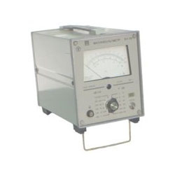
        My voltmeter. Scale is set to 10VRMS
        Shows output voltage (6.2VRMS or 17.5Vp2p) with input of 4.24Vp2p:


        Hope this helps somehow. Anyway -it was fun to test simulation vs real life

        Comment


        • Originally posted by habitbraker View Post
          Hello SB!

          Well, Im reading your experiments with quite a interest, so keep it comming
          Today was a rainy day and I had free time so I did your last experiment myself. Just to test if my real results match with simulated...

          Coil is unshielded. All setup on breadboard - like yours.

          I messured all parameters(C1,C2,L,Rl) with RLC so this was mt test circuit. My sig.gen. Rout=560R.


          My calculated resonance frequency(your formula) is 15.57KHz

          But I didnt use it in real test. Instead I messured output voltage and swept frequency. So resonanse is where biggest voltage was and it was about 15.9Khz. Match pretty nice with calculated value.

          Input voltage was 3VRMS = 4.25V(amplitude). With this input at 15.9Khz I got 6.2VRMS which is 17.5Vp2p.

          In simulation with same input I got 18.6Vp2p. So only about 1V error which is acceptable because of my RLC meter, Freq meter, Voltmeter errors which sum up. Also coil has some interwinding capacitance. My conclusion - it matched pretty good in my experiment.

          I retested with 2.1VRMS input (Amplitude 3V) and output was 4.1VRMS or 11.6Vp2p.
          Simulated one is 13.1Vp2p so around 1.5V error...

          This is how my test looked:


          My voltmeter. Scale is set to 10VRMS
          Shows output voltage (6.2VRMS or 17.5Vp2p) with input of 4.24Vp2p:


          Hope this helps somehow. Anyway -it was fun to test simulation vs real life
          Hi habitbraker!

          That is very interesting and encouraging -- I thank you for doing those tests . It gives me hope that maybe I'm doing something wrong in my actual circuit or have some bad components or connections. Your results match much better than mine.
          I will keep testing.

          Note1: I'm impressed if your voltmeter can accurately measure AC at 16 kHz. What do the specs on it say? My voltmeter specs cut off at a much lower frequency. What meter brand do you use?

          Note2: I use an oscilloscope for the voltage measurements. Do you have one you can confirm your measurements with?

          Note3: Your coil is higher resistance to start with than mine, but I also cannot match a simulation with 25 ohm coils, so I'm still puzzled at my end.


          Eventually I intend to drive the coil with a square wave using the circuit with push-pull transistors shown in an earlier message above. But I'd like to see some healthy voltage first in these sine wave tests!

          I'll try again.

          Best regards,

          -SB

          Comment


          • Originally posted by simonbaker View Post
            Hi habitbraker!

            That is very interesting and encouraging -- I thank you for doing those tests . It gives me hope that maybe I'm doing something wrong in my actual circuit or have some bad components or connections. Your results match much better than mine.

            I will keep testing.

            Note1: I'm impressed if your voltmeter can accurately measure AC at 16 kHz. What do the specs on it say? My voltmeter specs cut off at a much lower frequency. What meter brand do you use?

            Note2: I use an oscilloscope for the voltage measurements. Do you have one you can confirm your measurements with?

            Note3: Your coil is higher resistance to start with than mine, but I also cannot match a simulation with 25 ohm coils, so I'm still puzzled at my end.


            Eventually I intend to drive the coil with a square wave using the circuit with push-pull transistors shown in an earlier message above. But I'd like to see some healthy voltage first in these sine wave tests!

            I'll try again.

            Best regards,

            -SB

            Hi again!
            Well I tested it again with scope and it reads about 18Vp2p so even closer. But I have doubts about my scope accuracy because my tgsl voltage on it ai 17Vp2p not 16V.

            Anyway - My Voltmeter is accurate. It is old russian one - about 40years old. it can read up to 5Mhz.


            I hope you will get that voltage too.
            I looked at that push-pull simulation. It looks interesting - with 3V PS you get 45Vp2p. If use 8V PS you get 160Vp2p. I guess thts overkill Or not?
            Maby I could test that circuit too... if it helps??

            Comment


            • Originally posted by habitbraker View Post
              Hi again!
              Well I tested it again with scope and it reads about 18Vp2p so even closer. But I have doubts about my scope accuracy because my tgsl voltage on it ai 17Vp2p not 16V.

              Anyway - My Voltmeter is accurate. It is old russian one - about 40years old. it can read up to 5Mhz.


              I hope you will get that voltage too.
              I looked at that push-pull simulation. It looks interesting - with 3V PS you get 45Vp2p. If use 8V PS you get 160Vp2p. I guess thts overkill Or not?
              Maby I could test that circuit too... if it helps??
              Sure, if you would test it also I'm very interested; I seem to not have a great touch with real circuits.

              Those voltages are the kind of overkill I like! Especially from a low voltage supply. I'm interested in whether this kind of coil driver with higher voltage can help get a better signal-to-noise ratio in the RX circuit. (So long as the FCC doesn't come running...)

              It may turn out that the hi-Q circuit is very finicky as it goes over the real ground, and causes more problems than it solves. But maybe those problems can be compensated for if understood well.

              An interesting feature of this coil driver is that it seems to draw a fairly low current from the power source -- again due to the hi-Q circuit which doesn't dissipate much energy. But that is an engineering question that needs more looking into. The ratio of Cxa to Cxb seems to affect the efficiency (note that if Cxa/Cxb >> 1, it starts to become a simple series resonant circuit, and the supply output impedance becomes important).

              That is a cool voltmeter, nice specs!

              Regards,

              -SB

              Comment


              • I think I found my error in matching the simulation to my circuit.

                My simulation is actually using a 6 V pp sine wave (because I put in the amplitude as 3V), my actual circuit was driven by a 3 V pp signal.

                So I mis-matched the driving voltage by a factor of 2!

                So, after redoing the simulation with 3 V pp, I compare 9 V pp (simulated) with 7.5 V pp (circuit). I feel better already.

                However, this still indicates an equivalence to a coil with a resistance at resonance of 20 ohms, compared to the measured DC resistance of 7.3 ohms, about 300% increase (skin effect???).

                But I'll keep trying more tests see what is possible.

                By the way, I like to use the "calculated resonant frequency" for the simulation frequency to compare to the circuit resonance max voltage found empirically by tuning the signal generator. In other words, I don't plug the empirical resonant frequency into the simulation -- I feel that errors in the component values would come into play more.

                Regards,

                -SB

                PS Thanks again for doing your test -- I might never have noticed my error. Proves the value of forums like this...

                Comment


                • wrong thread! help? Qiaohzi?

                  To webmaster (Q):

                  All this stuff about resonant coil I meant to put in a different thread, this one:

                  http://www.geotech1.com/forums/showt...sl+experiments

                  Is there any way to move messages 656, 657, 658, 661, and 666 through 677 to that thread?

                  It would be better there, because it is not helpful to anyone troubleshooting TGSL.

                  Thanks,

                  -SB

                  Comment


                  • I think I've moved the correct posts. However, the move process only allows me to select one page at a time, and the posts get renumbered after each move. If any of them are wrong, please let me know. In general, please try to make your posts in the correct thread, as moving multiple posts can be somewhat tricky. I have already refused some previous requests due to the sheer number of posts that had to be moved.

                    Comment


                    • wrong thread! help? Qiaohzi?

                      Originally posted by Qiaozhi View Post
                      I think I've moved the correct posts. However, the move process only allows me to select one page at a time, and the posts get renumbered after each move. If any of them are wrong, please let me know. In general, please try to make your posts in the correct thread, as moving multiple posts can be somewhat tricky. I have already refused some previous requests due to the sheer number of posts that had to be moved.
                      Thanks Qiaozhi, sorry for that hassle, you did good.

                      Actually, there still are a few left in the old thread: 662 (http://www.geotech1.com/forums/showp...&postcount=662) through 665 (http://www.geotech1.com/forums/showp...&postcount=665) that belong over here -- it probably would be tricky to get them back in order, but dumping them at the end is good enough.

                      If you don't feel like moving them, I can try to make new copies just to have them for reference.

                      Thanks! I'll try harder to not make a mess in the wrong thread again!

                      -SB

                      Comment


                      • Originally posted by simonbaker View Post
                        I think I found my error in matching the simulation to my circuit.

                        My simulation is actually using a 6 V pp sine wave (because I put in the amplitude as 3V), my actual circuit was driven by a 3 V pp signal.

                        So I mis-matched the driving voltage by a factor of 2!

                        So, after redoing the simulation with 3 V pp, I compare 9 V pp (simulated) with 7.5 V pp (circuit). I feel better already.

                        However, this still indicates an equivalence to a coil with a resistance at resonance of 20 ohms, compared to the measured DC resistance of 7.3 ohms, about 300% increase (skin effect???).

                        But I'll keep trying more tests see what is possible.

                        By the way, I like to use the "calculated resonant frequency" for the simulation frequency to compare to the circuit resonance max voltage found empirically by tuning the signal generator. In other words, I don't plug the empirical resonant frequency into the simulation -- I feel that errors in the component values would come into play more.

                        Regards,

                        -SB

                        PS Thanks again for doing your test -- I might never have noticed my error. Proves the value of forums like this...
                        Hello SB!

                        Glad to hear that you found your mistake and also got fine voltage. I also got about 1-1.5 less than simulated in that test.
                        About skin efect - i dont believe that in such low frequencies it makes any big deal. It just real circuit I think.

                        About formula: if I understand correctly- in simulation you use calculated f0 (resonant) but in real circuit f0 found with tuning? Well.. i used tuned f0 in both...

                        about that push-pull circuit - I plugged it on the breadboard and tested a little bit. One question -whayt circuit did you actually use? I made a little modifications to convert to bipolar (my gen output) to single. Also removed those emmiter resistors couse imho it doest make big difference (that I can see - just lower voltage). But maby im wrong there - needs testing.
                        This is my final circuit:


                        Resonant circuit is tha same. f0 now is little lower - from 15.9 to about 15.7khz.
                        L1 dc resistance the same - 18.62ohms
                        Power supply - +8V regulated. from 12V battery
                        It gave interesting results - when input is lower than about 2Vp2p then output suddenly drops to zero. same in spice. Its not suprise because of two input diodes in series...

                        But most interesting is that biggest output voltage is when input is about 2.3Vp2p (just about cutoff point) If I increase it further (i can increase it up to 5.5Vp2p) output voltage decreases. It lowers to about 35Vp2p. In spice I dont see such decrease with increased input..
                        This is simulated, vs real life(input 2.3Vp2p. f0=15.75KHz, sim output=53Vp2p, real output=about 49Vp2p. (10V/div)):


                        (I hope that I didnt ruin whole page because of this long picture)
                        Pretty close I think.
                        Maby output stage needs a little biasing - to get rid of that nonlinear step in sine wave?

                        I didnt test any more - maby you could give me beter circuit and instructions what to test so that it could be more useful for you and TGSL modifications. Im big fan of TGSL and your work - thats why im doing this. All setup stays on my breadboard - so any change will be 1min question - yust ask.

                        Comment


                        • Originally posted by habitbraker View Post
                          Hello SB!

                          Glad to hear that you found your mistake and also got fine voltage. I also got about 1-1.5 less than simulated in that test.
                          About skin efect - i dont believe that in such low frequencies it makes any big deal. It just real circuit I think.

                          About formula: if I understand correctly- in simulation you use calculated f0 (resonant) but in real circuit f0 found with tuning? Well.. i used tuned f0 in both...

                          about that push-pull circuit - I plugged it on the breadboard and tested a little bit. One question -whayt circuit did you actually use? I made a little modifications to convert to bipolar (my gen output) to single. Also removed those emmiter resistors couse imho it doest make big difference (that I can see - just lower voltage). But maby im wrong there - needs testing.
                          This is my final circuit:


                          Resonant circuit is tha same. f0 now is little lower - from 15.9 to about 15.7khz.
                          L1 dc resistance the same - 18.62ohms
                          Power supply - +8V regulated. from 12V battery
                          It gave interesting results - when input is lower than about 2Vp2p then output suddenly drops to zero. same in spice. Its not suprise because of two input diodes in series...

                          But most interesting is that biggest output voltage is when input is about 2.3Vp2p (just about cutoff point) If I increase it further (i can increase it up to 5.5Vp2p) output voltage decreases. It lowers to about 35Vp2p. In spice I dont see such decrease with increased input..
                          This is simulated, vs real life(input 2.3Vp2p. f0=15.75KHz, sim output=53Vp2p, real output=about 49Vp2p. (10V/div)):


                          (I hope that I didnt ruin whole page because of this long picture)
                          Pretty close I think.
                          Maby output stage needs a little biasing - to get rid of that nonlinear step in sine wave?

                          I didnt test any more - maby you could give me beter circuit and instructions what to test so that it could be more useful for you and TGSL modifications. Im big fan of TGSL and your work - thats why im doing this. All setup stays on my breadboard - so any change will be 1min question - yust ask.
                          About skin efect - i dont believe that in such low frequencies it makes any big deal. It just real circuit I think.
                          I'm ignorant about how much skin effect is present at these frequencies -- but wondering what in fact causes the difference between the real circuit and simulation. Energy is lost somewhere; I agree, maybe just "not ideal" components. But LTSpice provides for some of those non-ideal parameters and I'm wondering which ones account for the real loss, in case we can improve the Q a little more, or at least simulate it better.

                          About formula: if I understand correctly- in simulation you use calculated f0 (resonant) but in real circuit f0 found with tuning? Well.. i used tuned f0 in both...
                          Yes, I tried to use the frequency in each case that would give max voltage, thinking that was a fairer comparison -- to protect against plugging an inaccurate component value into the simulation. But it should be very close anyway because Q is not so high a little freq shift matters much.


                          about that push-pull circuit - I plugged it on the breadboard and tested a little bit. One question -whayt circuit did you actually use? I made a little modifications to convert to
                          I'm currently driving my push-pull directly from my signal generator with a 0 - 3 V square wave, through the 1K resistor. I didn't use any other driver transistors as you did, though that seems good if you need to isolate your voltage source (which I might, as I plan to drive this from a microcontroller output port -- we'll see if necessary).

                          Is diode D1 useful? What is the purpose?

                          Because I want to be really cheap with battery power, I would like a driver that takes as little current as possible. But your arrangement looks pretty good (maybe only one transistor stage needed???), and takes the voltage pretty low (around .2 V probably?). I'd of course prefer going all the way down to the ground rail if possible.

                          There is an asymmetry in using the driver transistors however -- in the "high state", the push-pull is driven through 4.7K + 1K, and in the "low state", it basically is driven by just 1K (sink). So I'm not sure whether that is the preferred way to drive the push-pull.

                          Also removed those emmiter resistors couse imho it doest make big difference (that I can see - just lower voltage). But maby im wrong there
                          I don't actually put those emitter resistors in the real circuit -- I just put them in the simulation so I could measure the current through the branch -- I didn't know how to pick off the transistor emitter current in LTSpice, but I think I can now, you just have to move the cursor carefully. So I'm same as you with real circuit.

                          But most interesting is that biggest output voltage is when input is about 2.3Vp2p (just about cutoff point) If I increase it further (i can increase it up to 5.5Vp2p) output voltage decreases. It lowers to about 35Vp2p. In spice I dont see such decrease with increased input..
                          Not sure why that happens either, because it seems your transistor drivers act like a switch that should make same pulse regardless of input voltage. If your signal generator changes frequency for some reason, that could cause it.

                          This is simulated, vs real life(input 2.3Vp2p. f0=15.75KHz, sim output=53Vp2p, real output=about 49Vp2p. (10V/div)):
                          That is outstanding agreement, so I feel hopeful that this can be a useful circuit, I appreciate your confirming it (and making a superior practical circuit).

                          One little addition I'm studying, but I can't convince myself whether it is useful or not -- that is a small choke coil in the branch to the resonant circuit (see attachment). In the LTSpice simulation, it seems to cut down a current spike, but on my oscilloscope I never see that spike. And in the real circuit (and LTSpice), the choke makes some little oscillations that perhaps could cause some noise problems later on. So just an idea.

                          My other questions are what are the best component values, resistors and even the resonant capacitors. You can increase the current in the coil a little with some different values (depends on impedance of your power supply though), but the values I picked so far seem to be a good tradeoff between battery consumption and coil current.

                          Your tests have been very helpful for sure. I'm going to try soldering up a protoboard circuit and try to work it with a microcontroller -- will probably take a long time because I'm new with the microcontroller.

                          If you have any other thoughts or ideas, let them fly.

                          Regards,

                          -SB
                          Attached Files

                          Comment


                          • Hello again SB!

                            Thanks for tha answer.

                            Now I undersatand what was your circuit. I used this, because my generator dont give single polarity square wave so transistor was needed. With single transistor there was lower output voltage (i think you are correct- it didnt rail up and down completely). Also correct about C resistor influance on driving current.

                            About diode- well, in spice it works without (and in real also might), but those small signal tr (I used BC547 instead of 2222) have B-E breakdown of about 6V so if driving with bipolar square - all negative (for npn) part drops on this b-e. So just protection...

                            I will try to find if those drivers output change when input is change. About frequency - I dont think that it changes when output level is changed. Something else.

                            About choke - Ill try something

                            What mcu are you using? I have some exp with PIC micros and also have way to program those. You are planing to drive push-pull with it? Just generate pulses? That could be easy to code - so i coild try it also. Also it could give better stability (using quartz) and nicer driving squares. Also single polarity, so eleminates those drivers.

                            Anyway - I will try

                            oh I forget - that test circuit current consumtion was about 9mA.

                            Comment


                            • Originally posted by habitbraker View Post
                              Hello again SB!

                              Thanks for tha answer.

                              Now I undersatand what was your circuit. I used this, because my generator dont give single polarity square wave so transistor was needed. With single transistor there was lower output voltage (i think you are correct- it didnt rail up and down completely). Also correct about C resistor influance on driving current.

                              About diode- well, in spice it works without (and in real also might), but those small signal tr (I used BC547 instead of 2222) have B-E breakdown of about 6V so if driving with bipolar square - all negative (for npn) part drops on this b-e. So just protection...

                              I will try to find if those drivers output change when input is change. About frequency - I dont think that it changes when output level is changed. Something else.

                              About choke - Ill try something

                              What mcu are you using? I have some exp with PIC micros and also have way to program those. You are planing to drive push-pull with it? Just generate pulses? That could be easy to code - so i coild try it also. Also it could give better stability (using quartz) and nicer driving squares. Also single polarity, so eleminates those drivers.

                              Anyway - I will try

                              oh I forget - that test circuit current consumtion was about 9mA.
                              About diode- well, in spice it works without (and in real also might), but those small signal tr (I used BC547 instead of 2222) have B-E breakdown of about 6V so if driving with bipolar square - all negative (for npn) part drops on this b-e. So just protection...
                              Good idea, I wouldn't have thought about that. I didn't know such a low breakdown. I seem to recall people use transistor junctions as zener diodes in a pinch...

                              I will try to find if those drivers output change when input is change. About frequency - I dont think that it changes when output level is changed. Something else.
                              It's a good mystery... keep at it and let us know what it was!

                              What mcu are you using? I have some exp with PIC micros and also have way to program those. You are planing to drive push-pull with it? Just generate pulses? That could be easy to code - so i coild try it also. Also it could give better stability (using quartz) and nicer driving squares. Also single polarity, so eleminates those drivers.
                              I have the Texas Instruments "LaunchPad" MSP430 platform ($4.30 mail order!) that comes with two processors (one with a 10 bit A/D converter), an optional crystal, and some headers for interfacing with a PCB/protoboard of your making. They got me because it was so cheap -- but lots to learn.

                              The processor operates on about 3 volts, so I plan to drive the push-pull coil circuit with an output pin (0 to 3 volt square wave). I may need to think about pull-up/pull-down resistors and/or current sourcing capability (I think those pins can source enough mA, but will need to check). So I may need extra transistors like yours.

                              I can optionally use a higher voltage for the coil, or the same voltage for the coil push-pull and microprocessor. I'd like to check out using the same voltage first.

                              To not be naive, I realize that the MSP430 is probably a hundred times too slow, the A/D needs 10 more bits resolution, the memory is a hundred (thousand) times too small, and a hardware multiplier would really help. It will be interesting to see what can be done, all tricks fair play.

                              There are upgrade paths to somewhat more powerful MSP processors, but still not really powerful. The nice thing about the MSP430G2231 (the chip I'm planning to use) is it costs about 25 cents! I like cheap.

                              oh I forget - that test circuit current consumtion was about 9mA.
                              I think it's pretty amazing to get that kind of coil voltage for 9mA. Tweaking component values can get other tradeoffs as mentioned before.

                              I'll be interested in anything you do with the circuit.

                              Regards,

                              -SB

                              Comment


                              • Hello SB!

                                I played a little with my circuit today too.
                                I found reason why output voltege was lowering with input increasing - my sig gen fault. Its dutty cycle was changing when level was changed. Well it is DIY anyway Sine output is perfect at least.

                                I tried a small chokes in the output - didnt see improvements. Small oscillations appiered instead of sharp edges.Or Maby its better ?

                                I coded a fast pic code to generate 15.75Khz square and put it on the input. Output still 50Vp2p.

                                It connected other coil to the scope (10n parallel) and tried nulling and it looked very good. I could manage almoast zero null voltage. It was just fast and dirty test - didnt even remember actual numbers

                                One interesting thing. In ltspice this diode (see attachment) added 7V p2p (almoast 60Vp2p), but in real circuit it didnt make any difference. I dond know why. Even not shure what this diode does in sim?

                                I have one blank eduardo PCB. Maby it is worth trying solder one but instead of colpitts use this oscillator? But Im too lazy to solder right now . Its too early i think..
                                Attached Files

                                Comment

                                Working...
                                X