
 Tweet
Tweet
Originally posted by ivconic
View Post
-
Your posts are always helpful ivonic... I will make it -
https://www.geotech1.com/forums/foru...235#post102235Originally posted by ivconic View PostComment
-
........................
..... one of the trimmers on the pcb is crucial for setting the phase.
........................
Dear Ivconic,
Could you please specify which exact trimmer did you mean, so as to "play" with it and to get the most out of it?
It would be like a pleasant surprise for one to find that the average performing detector has unrevealed potential. How did you spark the curiosity, a?
And, one more issue - the influence of putting additional resistor (470 ohm) in the generator. Does it mean, that in the similar schematics (magnum redu, wave...), the feedback resistor, whose value varies widely 300k-390к) has the same role and influences in the same way on the ratio depth-stability?
Regards.Comment
-
Here's a part of the schematic extracted from that pcb , so judge for yourself:
Comment
-
Where and when exactly I said that?Originally posted by getsa View Post
...
What I wrote is this: "...So I've had the practice of retrofitting a switch on the front panel with which I change that 470 resistor with smaller values..."
Comment
-
Thank you for your responsiveness.Comment
-
-
Dear Ivconic,
Could you discuss the role (necessity/purpose) of the R-C-R circuit put in parallel of the TX LC circuit (470-68n-1k)?
I`ve made detectors with that exact generator and LC circuit, and they work very well. That`s why I`m curious about the influence of these additional components to the generator`s behavior and the overall performance of the detector?
Thanks in advance for any hints and tips you would suggest!...Comment
-
I think a potentiometer makes more sense 1-5k instead of a 1k resistor thus, noise from the outside environment is removed by a small change in frequency ,by changing the basic seed marked in red the smaller the phase shift in ch for discrimination..Nothing is noticeable in the air, but I'm not sure how much it worsens the discrimination on the ground ? Maybe it penetrates deeper into the soil, but with less discrimination..Comment
-
Indeed Orbit,
The same idea pop up in my mind right after Ivconic mentioned the importance of one of the trimmers for the depth. On one hand, few weeks ago I did some experiments with buried small coin (18mm diameter on 22sm in the ground), and noticed that rotating above the target there are directions/approaches when was heard unequivocal and definite reaction, and continuing the movement around the target in a circle there were moments, when the detector discriminated it partially. These two facts provoked me to check this kind of schematics in my archives, and it was confirmed that in most cases the component you have encircled in red is trimmer instead of constant resistor. I hadn't been paying attention on that so seriously, even though, back in time, I`ve repaired detector based on that sch solution, and there definitely was trimmer, because I`d redrawn back its schematic from the PCB. So, I definitely will play with that issue during some of the next weekends, as to confirm or dispel doubts on the matter (Moreover, the coin is still in the ground and is waiting to be found easily and clearly).
Cheers.Comment
-
I think the trimmer that ivconic refers to is a 1k one, which is not in the original IDX schematic, and was added in the RX circuit, also mentions that the tests were with a CZ5 coil.
Install this trimmer on my IDX, and you get an improvement in sensitivity, The GB and VDI varies a bit but it is within the range, my coil is homemade.Comment
-
Hello, I have two questions:
1- Is Tx coil capacitor which is 1uf mounted inside the coil , or on pcb.
2-What kind of bucking coil wire , is it like the tx wire or the RX coil one ?
Thank you BrothersComment
-
In my case, i just solder capacitor on connector inside pcb enclosure. Reason for that is cause later u can change frequency by changing capacitors.Originally posted by ifrenide View Post
Btw, 330n TX capacitor and 10n for RX for me works much better, higher frequency i found is better for my soil where i hunt for tiny roman coins...
RegardsComment
-
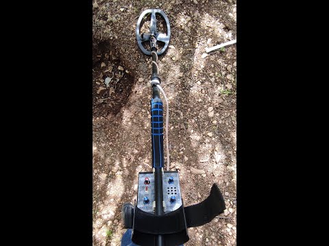
hi freinds
please i need for help
what is the problem here
https://www.youtube.com/watch?v=MmMzdhT6w3U
Comment
-

Comment