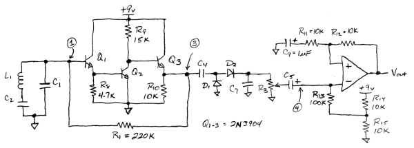
Here is a possible solution for the two-box receiver. I say "possible" because I never fully tested it.
As I said in a prior post, the CA3035 is a simple 3 amplifier chip. Each amp is essentially a common-emitter stage, the first two having follower outputs as well. One mistake I made was in the gain-bandwidth of the amps: they have lots of bandwidth, so the two-box receive circuit could probably get nearly the entire 129dB of gain except that the 3rd stage is not loaded optimally. The 3035 is so simple you can easily replace the whole thing with discretes, using resistor dividers and degeneration to bias the stages instead of current mirrors.
In my RX circuit, I essentially duplicated the first amp of the 3035 because it needs the high gain at 180kHz, something a little difficult to do with el cheapo opamps. So this stage should give about 48dB of gain (250) pretty independent of the resistor values (R8-10). R1 is simply used to bias the amp, and I simplified this a little as the extra cap and resistor (R2,C3) in the original circuit do not do anything - I think they were copied from a circuit in the data sheet. I've probably biased this stage hotter than it needs to be, and R8-R10 can be increased to reduce currents while not affecting much else. Doubling their values should be safe.
The diode detector stuff is the same, but now the pot (R3) feeds a non-inverting amp with a gain of ~220. This can be a cheap opamp as we are now down to audio, not 180kHz, and anything with 1-2 MHz GBW product will do. Remember though, we want to run off a single battery so the opamp should be single-supply capable, like the LM358 (Plug: ADI has some excellent single-supply opamps, I like the AD8031). I've included R13-R15 to bias it to a midpoint voltage.
At this point I've stopped the circuit. There is only about 95dB of gain so you probably want another stage. This can be another LM358 stage (it's a dual opamp anyway) or, if you want to drive a regular speaker, you can tack on an LM386 or similar audio amp.
I did test the first stage replacement, including the diode detector. I did not have an AM modulated TX signal so I rigged something up. What I found is that the cap C7 might be too high - it seemed to only want to pass extremely low audio, ~10Hz. I stuck in about a 1nF cap and it seemed to work fine in the kHz range. May have been a problem with my diodes tho. I did not go any further, so there is probably some debug left to do. If anyone completes this design let me know and I'll post a final circuit.
