Announcement

Collapse
No announcement yet.

Surf PI that likely will be apprehended....

Collapse
X
 
  • Filter
  • Time
  • Show
Clear All
new posts

  • Surf PI that likely will be apprehended....

    Hi,

    First of all I want to give congratulations to the all members for the excellent work developed here.
    What led me to try to find information about a homemade metal detector, was the Portuguese legislation, because it does not allow detection on the beaches.
    Do not wanna lose my GoldmaxxPower V4 or my Minelab Explorer SE, to the cops and still carry a heavy fine.
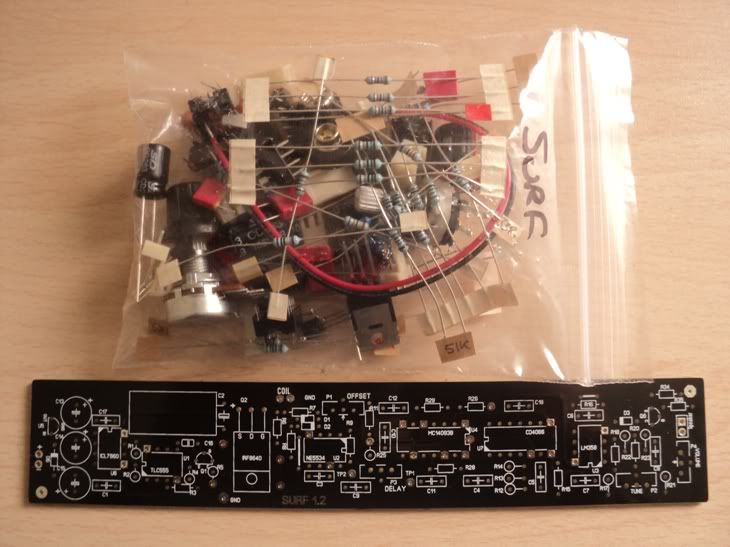
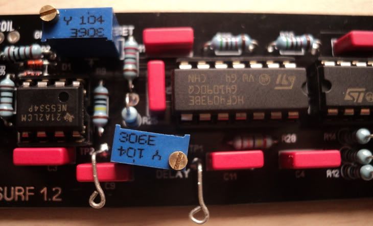
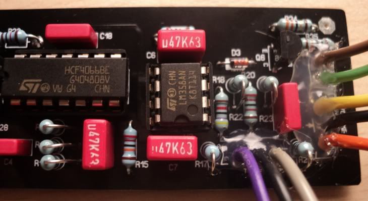
    IGSL I think is a little advanced for me to start building, so I had thought about the Surf PI. I have all the equipment needed for construction.


    I would like to make this topic a well detailed step-by-step, to help my detecting Portuguese colleagues and of course all those who have little knowledge and want to follow your design.
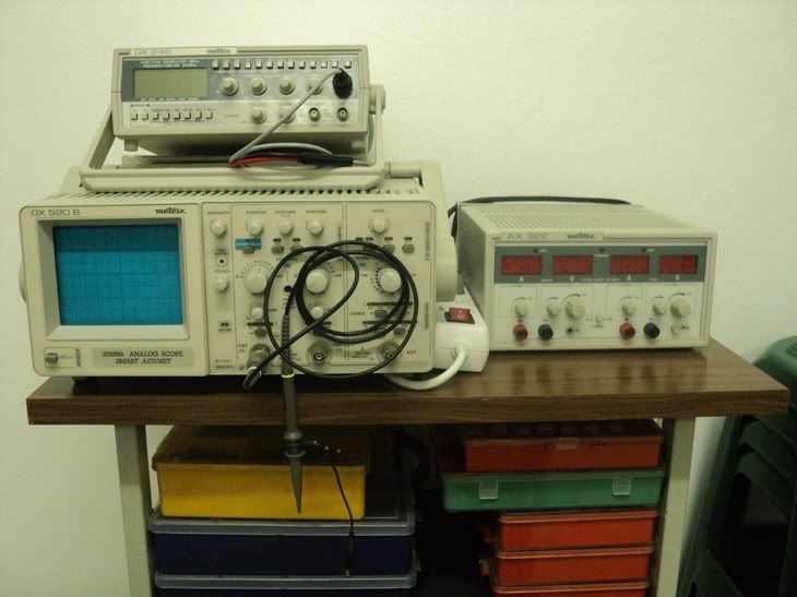
    Expect lots of questions, even using the oscilloscope that is new here at home (never used one).
    The next step will be to purchase a longboard from Silverdog's shop.

    Best regards
    Nezocas

  • #2
    Hi there,

    I just received the Surf Kit


    What is the proper way to assemble it... Do I have to weld a specific part of the circuit and make the necessary adjustments, before proceeding to solder the remaining components, or can I solder all components on the board and make all the necessary adjustments only in end of the whole kit assembled..?

    Best regards
    Nezocas

    Comment


    • #3
      Solder everything on and make adjustments after.

      Comment


      • #4
        My self I like to Load and solder all Power supply components.

        Apply battery and check all points for correct power.

        Don't forget the issue with R18 and R22!

        Comment


        • #5
          By looking at the kit there silverdog sent you, dont think you can go far wrong, even the resistors are marked up so you you dont even have to read the colour codes, all component values are marked on the pcb so just follow them carefully .
          If you have never soldered before get a bit of wood and hammer in some panel nails, there copper looking with very small heads, once you done that get some wire, 13amp fuse wire size and do one wrap round per nail following through.
          The art of soldering is 1st make sure everything is clean ,2nd a skim of solder to the iron bit, 3rd apply iron bit to area to be soldered, 4th feed the solder through the joins not the iron bit, 5th once the solder has run between component and pcb print pull away the job is done.
          Ive seen some very clever engineers who actually cant solder properly, the common problem is instead of going in and out of the event in short time as possible they doodle with it either the solder hasnt run or they have crucified the component and pcb which ends up what we call in the trade as bird ****, ie instead of a nice smooth joint its splattered.
          If your joining two wires as previous make sure there clean then tin both wires before joining them together and then the same applys iron bit on joins then feed a small amount of solder through the joins not the iron bit.
          The iron bit is to melt the solder and heat the items your soldering, nothing more nothing less.
          Im sure you will do ok just treat the parts as fragile, dont keep bending the leads back and forth on them and dont roast them.
          This takes me back a few years,with the nails idea my dad had me doing it when i was 11, but was a normal way of training in those days.

          All the best

          Comment


          • #6
            Originally posted by homefire View Post
            My self I like to Load and solder all Power supply components.

            Apply battery and check all points for correct power.

            Don't forget the issue with R18 and R22!
            These are a new batch of boards with corrected R18 / R22 silkscreen

            Comment


            • #7
              Hi,

              First of all I have to thanks to Silverdog....what a superb Kit, because I forgot to thank him, upon the Kit arrival.
              And then thanks to the excellent tips you have all indicated so far.
              Will report soon.

              Regards

              Comment


              • #8
                Hi,

                I just solder every component in its place
                Used as a reference the list of components in Silverdog store, I think its very hard to make a mistake.
                I leave some photos for quick evaluation and where I will describe the difficulties encountered.

                In this first picture I had some difficulty in placing the C16 and R3 due to the area being overcrowded by IC U1


                In this second picture, I chose to put the jumper wire, as some colleagues advised in other topics.


                Here too, had difficulties in placing the Delay potentiometer in place, because I had to let it twisted to one side.....I also noticed that some Members leave this one on the outer box ....is really needed?

                Also left 2 hooks to perform the calibration, after that will be removed ....


                In this photo you can already see extensions to the tune / volume / speaker
                Here I will need help because I do not know which color should I connect to which leg of the potentiometers


                What are the next steps to take... connect the potentiometers .... power the board up and make adjustment / testing.....or start to build the coil

                Best regards
                Nezocas

                Comment


                • #9
                  Hi,

                  Made a quick coil with 0.40mm wire 200mm diameter 30 turns and 3.5homs
                  Connected the board to a 12V supply, and I cant get under 1.4Vdc with offset pot...ground lead was on TP1
                  Under pin5 of the 7660 I got -4.61Vdc, ground was on IRF casing

                  A little help would really come in handy
                  Regards
                  Nezocas

                  Comment


                  • #10
                    Your assembly looks good in the pic, but check for solder bridges on the other side. I am not familiar with this circuit, but it is more normal for the ICs to point the same way. In the pic where you show the two calibration hooks, the two ICs have the index facing each other. Is one perhaps incorrectly inserted in the socket?

                    -Ed

                    Comment


                    • #11
                      The 2 IC's facing each other is ok, thats just the pcb layout,
                      what works for me is the digital multimeter negative lead on battery ground
                      and the positive lead to pin 6 of the 5534, you should be able to adjust it
                      to zero volts.

                      Comment


                      • #12
                        Hi,

                        Thank you so much 6666
                        Ed in SoDak I have all coponents in the rigth place .... even the wire bridges near the IRF and C6

                        My multimeter ground lead was in the wrong place 
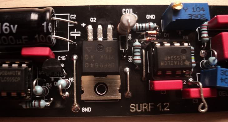
now I have zero Vdc under pin 6 of the 5534
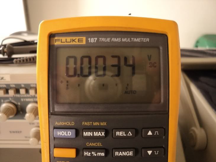


                        How can I adjust the delay pot with my scope....
                        What are the best specs for the coil,... coil diameter / wire AWG / PVC stranded wire or single Enamelled wire / homs to achieve

                        Best regards
                        Nezocas

                        Comment


                        • #13
                          you may have too many turns on your coil, try about 21 turns

                          see here http://www.geotech1.com/forums/showthread.php?t=19051

                          and here for delay help http://www.geotech1.com/forums/showt...t=17240&page=2

                          Comment


                          • #14
                            Hi,

                            Thank you all for the tips
                            Made a coil with degaussing wire from Tv set with 21 turns, 25cm diameter and 2.7Homs (too high).....I hit an Euro coin 25cm in air test


                            Power consumption was


                            Them made this one with speaker wire 12cm ID, 25cm OD, 20 turns and 0.2Homs.....also 25cm for an Euro coin


                            Energy consumption increased significantly


                            I'll try to redo this coil with single wire to increase Homs and reduce weight

                            Regards

                            Comment


                            • #15
                              congradulations you got it to work first time, like the idea of using degausing wire from a TV, got a few put back here from years ago, that was my secret lol.
                              Another wire you can try which ive used in the past is the wire from the scan coils, most are good quality insulation due to the high influx of voltage and current they had to handle, far in excess to what we are using them for.
                              You will find theres two lots of windings, the heavy gauge was fed from the line output stage of the TV that gave you the horizontal scan, the lighter windings was driven from the frame output stage which gave you vertical scan.
                              So for your PI go for the linescan side of the coils which are used to handling around 1000v.
                              If you got the whole TV and its plastic remember you can make good project enclosures out of them, ive just used part for my Mini pulse 3 im building.
                              Also alot of the older TVs used 32-35ohms speakers which are handy with alot of projects on here not to mention the wiring looms, plugs sockets switches etc.
                              And while your striping it check inside the tuner assembly, you maybe lucky and find a BFR199 inside which with that and the housing will build you a very nice universal coil tester which I posted the full project on here.

                              Word of warning, be careful with the tube as they will implode if you drop it on its face.
                              If you feel the need to discharge it just knock the neck off with pliers or something.

                              All the best

                              Comment

                              Working...
                              X