Announcement

Collapse
No announcement yet.

My Homemade VLF Detector

Collapse
X
 
  • Filter
  • Time
  • Show
Clear All
new posts

  • #76
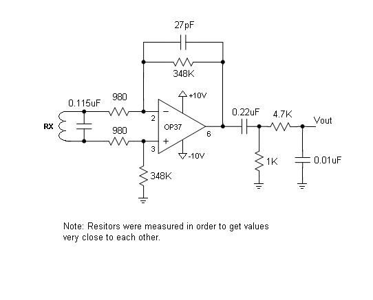
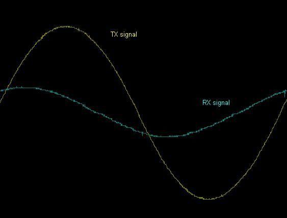
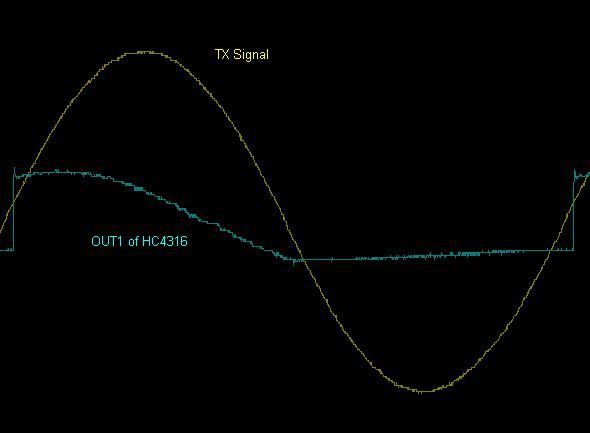
    Preamp circuit is just good enough, and regarding microvolt levels, you just need to detect microvolt change imposed to some residual signal level, not to absolutely detect that signal level above noise floor. Mostly not involving input amp, but later stages. This change is closely related to MD motion mode response, gain is achieved in relatively narrowband low frequency circuits, later ,after demodulator stage. Immediately after demodulator (sync detector) stage, signal is DC, static, varying according to X or Y amplitude in that channel. Next stage is single peak when coil is swept over target, last stage is “second derivative” response, going first down, then to positive, and again down, this positive part is what is detected.

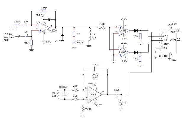
    So this is “secret part” in all this, very small changes, uV level, detected when imposed on 1000 times or more stronger unbalance or ground signals (still milivolts), in dedicated detector circuit.

    At something like 350x gain amplifier, 1Vpp means reasonably good coil balance, but you not need that high gain here, compensate later, this way “dynamic range” will be compromised, even strong ground mineralisation component can saturate input stage, then, game is over, no matter what you do after that.

    Dynamic range! May look pointless with comparator circuits, but it is not! (perhaps more competent people on this forum can explain this in more details)

    Comment


    • #77
      Originally posted by JamesPicard View Post
      So far my experiments on the workbench are saying I do need uV sensitivity, unless there is some secret that I am not understanding.

      Using the Volt Peak function on my o-scope, it gives me readings in millivolts. I can detect a coin about 4 cm away because I see the scope change by about 2 mV. If I am going to be able to detect coins 20-30cm away, it seems I certainly need to be able to detect a change in uV.

      Here is my preamp circuit now which allows me to see a change in millivolts. But still not good enough.


      Measuing Vout, it is normally about 1Vp-p with no coin around the ring.

      Davor, I heard what you are saying, and understand all the words, but don't have a clue what it means. Maybe after a few sips of wine it will make sense.
      Your preamp has a gain of 51dB, which is far too high. When even a medium sized target gets close to the coil, your preamp will saturate and you will not be able to detect the change in signal level. In effect, your detector will not "see" any targets close to the coil, except for a little bit of chatter as it approaches the target.

      As I suggested before, start off with the preamp from the TGSL and take it from there. You can be assured that metal targets will be detected at a reasonable distance, despite what you're currently finding with the oscilloscope. At the moment it will only take 2.8mV at the input to cause saturation.

      Comment


      • #78
        Originally posted by Skippy View Post
        You are not looking for microvolt signals, you are looking for microvolt changes to millivolt signals, hence you don't need gains of 10's of thousands (that would simply saturate your amplifier) just a pre-amp gain of 50 to 200 would be typical, and enough....

        Hmm.... now, that is interesting. I think the light is coming on now.

        Correct me if I'm wrong, but it sounds like you are saying I don't want to amplify the raw voltage right off of the RX coil, instead I need to amplify "the voltage change" that is above the "normal" Rx voltage. Is that what everyone here is trying to tell me?

        Comment


        • #79
          Originally posted by Qiaozhi View Post
          ...As I suggested before, start off with the preamp from the TGSL and take it from there. You can be assured that metal targets will be detected at a reasonable distance, despite what you're currently finding with the oscilloscope. At the moment it will only take 2.8mV at the input to cause saturation.
          Ok, I'm backing off on the gain, but not sure why you said 2.8 mV would cause saturation. The gain is 350, so basically 2.8mV * 350 or about 1 V.

          (Edit: Hmm....well, thinking this over I suppose you mean it is going to cause saturation "later on" in my circuitry because there is going to be more amplification down the chain ???)

          Comment


          • #80
            Originally posted by Tepco View Post
            ...you just need to detect microvolt change imposed to some residual signal level, not to absolutely detect that signal level above noise floor. Mostly not involving input amp, but later stages. This change is closely related to MD motion mode response, gain is achieved in relatively narrowband low frequency circuits, later ,after demodulator stage....

            ok, now I'm starting to get it.

            Comment


            • #81
              Originally posted by JamesPicard View Post
              Ok, I'm backing off on the gain, but not sure why you said 2.8 mV would cause saturation. The gain is 350, so basically 2.8mV * 350 or about 1 V.

              (Edit: Hmm....well, thinking this over I suppose you mean it is going to cause saturation "later on" in my circuitry because there is going to be more amplification down the chain ???)
              You're correct; that was a typo. It should have read 28mV.

              Comment


              • #82
                Here's my design so far. I added the a comparator circuit using LM318s. These have a high slew rate so they can switch fast enough for the 16.5KHz signal. The diode outputs are just to clip off the negative half and use as control signals for the 74HC4316 (analog switch).

                I have a question about the output from the HC4316. Since the Rx is out of phase from the Tx waveform, it causes the output of the analog switch to get some of the negative cycle. So I'm not really getting the half cycles, but pieces.

                I can't really tell if the TGSL has the same issue...don't I need to get the TX and RX back into phase so that the comparators and analog switches will work correctly?

                Here's what I'm seeing on the scope. In Pic1, this is showing the Rx signal in relation to the Tx signal.

                In Pic2, this is showing how the out-of-phase signal causes the analog switch outputs to have a shifted result. I was expecting to only see a positive half cycle.


                Present schematic


                Pic1 - Tx coil vs Rx signal out of LF353


                Pic2 - Tx Signal versus Pin2 of 74HC4316

                Comment


                • #83
                  Originally posted by JamesPicard View Post
                  Here's my design so far. I added the a comparator circuit using LM318s. These have a high slew rate so they can switch fast enough for the 16.5KHz signal. The diode outputs are just to clip off the negative half and use as control signals for the 74HC4316 (analog switch).

                  I have a question about the output from the HC4316. Since the Rx is out of phase from the Tx waveform, it causes the output of the analog switch to get some of the negative cycle. So I'm not really getting the half cycles, but pieces.

                  I can't really tell if the TGSL has the same issue...don't I need to get the TX and RX back into phase so that the comparators and analog switches will work correctly?

                  Here's what I'm seeing on the scope. In Pic1, this is showing the Rx signal in relation to the Tx signal.

                  In Pic2, this is showing how the out-of-phase signal causes the analog switch outputs to have a shifted result. I was expecting to only see a positive half cycle.
                  The TGSL expects the RX signal to be out of phase from the TX by about 20 degrees. You can also see from the TGSL schematic that the position of both samples can be adjusted by potentiometers. In your case, a lot depends on what you're planning to do with the sampled signals. If you were planning to build a simple T/R detector, then you can get away with only one sample. However, if your plan is to jump head first into creating a detector with ground balancing capability, then things get more complicated. In that case you would do well to simply copy the same setup as the TGSL, and understand how that works, before proceeding further.

                  Comment


                  • #84
                    Yes, I saw the pots there for the signal. But that appears to be simply for ground balancing. So I don't see how the TGSL is dealing with the problem...looks like it has the same issue as I do. So, it looks like the TGSL could be better if the timing is tweaked a little so that the "full half cycle" is used instead of a part of it.

                    Comment


                    • #85
                      Originally posted by Qiaozhi View Post
                      ...In that case you would do well to simply copy the same setup as the TGSL, and understand how that works, before proceeding further.
                      One of the design problems I noticed with the TGSL is it is using the LM393 comparators. It is a very slow part, unable to switch fast enough to get a nice quick transition at the zero crossing point. The LM318 is guaranteed to be 50V / uSec min, so I get an excellent transition (high to low, or low to high) right at the zero crossing point.

                      Comment


                      • #86
                        Oops! Too many sips of wine. The LM393 is not too slow. My brain is. (I forgot the pullups)

                        Switching back to LM393s.

                        Comment


                        • #87
                          ok, I changed my circuit over to the LM393s. I basically copied the circuit from the TGSL schematic.

                          But I still don't get it. The TGSL design behaves just like my circuit above with the Out of phase waveforms.

                          The Tx signal used to create the CTRL signals for the analog switch is out of phase with Rx signal. I thot the purpose of the LM393s along with the analog switch is to seperate out the positive cycle and the negative cycle. Then those 2 half cycles get changed over to dc levels. But due to the phase difference, one gets whole sine waves in both legs of the circuit. So, now I'm confused....whats the need for this circuit?

                          Comment


                          • #88
                            The two phase detectors would normally be switched 90 degrees out of phase with each other, and this would be preferred if you plan on feeding the signals into a micro. So one detector averages a positive half-cycle, the other quarter-of-a-cycle positive and quarter-of-a-cycle negative, if that makes sense. By then averaging this signal by low-pass filtering, you get a DC value (bandwidth of up to 100Hz maybe).

                            Comment


                            • #89
                              One thing that need clarifying - you are looking to demodulate the signal caused by the TARGET, at 0 and 90 degrees. Because the high residual coil null signal could have any phase relationship to the TX, the 'standing output' from your demods could be anything. To check the response to a target, you need a target with a known phase angle. Your first test item should be a ferrite item, such as a rod from a medium wave radio, though EMI suppression ferrites should be OK at low (10KHz) frequencies, and power ferrites from PSU transformers will be OK. These have a phase shift of Zero degrees. If you use a rod, use it end-on, ie. approach the tip of the rod to the centre of the coil, don't use it flat-on. Finding a 90 degrees target is hard, and it would generally be small and give a small signal, which is not what you want at this stage.

                              Comment


                              • #90
                                ok, I'll keep that in mind. Currently, others here told me I should concentrate first on just amplitude (detection) in stead of phase shift (discrimination). So I sort of ventured off on my own design now. I'm able to detect an American quarter at 24 cm now. I can detect my little alumin flashlight at about 33 cm. But I notice that the whole design is very sensitive to even my hand. If I move my hand to within 2 - 3 cm, I can detect that. No metal in my hand, tho.

                                Are commercial VLF detectors also sensitive to other non - metalic objects like this when they are close to the coil, or have I created a human detector now?

                                Comment

                                Working...
                                X