Announcement

Collapse
No announcement yet.

My Homemade VLF Detector

Collapse
X
 
  • Filter
  • Time
  • Show
Clear All
new posts

  • #16
    Originally posted by JamesPicard View Post
    Well, I think that ACE250 schematic floating around here has quite a few errors.
    The only problem with this design is that it is not truly differential. The non-inverting input impedance seen from the tank is 224.7k, while impedance seen from the inverting input is roughly 4k7/2 (due to feedback). Such opamp is amplifying a voltage across the tank, but also E-field phenomena, such as touching it, electrostatic discharges etc.
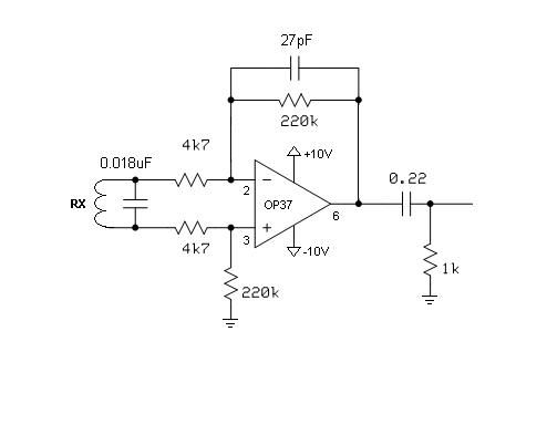
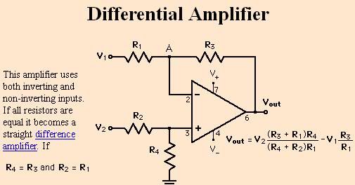
    It is quite easy to make it better. Resistors in the non-inverting branch must be replaced by much lower values to make the opamp work as a true differential amplifier. I'd replace 220k with 2k2, and 4k7 with 47ohm. Tank loading should not be a problem because total impedance seen from it should be over 4k, which could only be beneficial regarding noise.
    Whit true differential opamp you should not have problems typical for unshielded coils.

    Comment


    • #17
      Not to mention the fact there is a 27p cap across one of the 220K resistors, and not the other....
      I would recommend running your tx oscillator at 6.5KHz, and tune the rx coil to 8.5 - 9KHz.

      Comment


      • #18
        Ok, I'll increase the tuning cap on the Rx side to around 70nF and see what happens. I played around with frequency earlier. I tuned the Tx from 1KHz to 17KHz. Basically, at around 1-2KHz there was a flatline output....as I increased it, the output signal across the 1K resistor continue to increase all the way to 17KHz.

        Also, thanks Davor on that input....this is what I understand to be a Differential Amplifier but from what I remember years ago....one has to work at getting close to a workable Diff amp. I'll play around with your ideas, but I almost copied the circuit from the design that Qiaozhi showed me....I think that design has been verified as very good....However, I recognize that I'm not using a JFET op amp. So I think I'm going to need to order the LF353. The input bias current of the LF353 is in pAmps...my OP37 is typ 8 nAmps. So the LF353 is more sensitive by a huge amount.

        One thing about resonance...I thought if I hit resonance, I would get to a freq where I would see the output peak, but then begin to decrease as I continued to increase the frequency. Maybe if I modify my sine wave generator circuit so that I can get up to around 30KHz I'll finally see that peak occur and then fall back down.

        Comment


        • #19
          I looked at a differential amplifier circuit on the web...It looks like my Rx circuit is fine as far as the resistor matchups.

          Davor, I'm not sure I understand what you were explaining....?

          Comment


          • #20
            You better aim at some opamp that has good noise performance in input impedance range your application calls for. NE5534 or dual NE5532 and such. E.g. your coil is ~4mH, and at 17kHz its reactance is ~400 ohm. With 4k opamp input impedance you have some room for moderate Q resonance, however, it is much better to tune a tank a bit above the Tx because Rx coil's voltage response will be flat up to resonance, and phase response will be very timid.

            Comment


            • #21
              Regarding the true differential amplifier please check the attached PDF document and seek "The True Diff Amp". You'll also find here my LTspice simulation you may play with, and some ready values for some chosen gains.
              Attached Files

              Comment


              • #22
                Ok. You're trying to drive us all nuts, correct? Well, you can't drive me nuts. I won't even get over-torqued.

                But, how are you planning to fit a LF353 dual opamp into a OP37 (single) slot? You would want a single LF351 or maybe a premium IC like LF357. (Or maybe just leave the opamp alone for now?) OP37 has LOW bias currents, maybe not as low as your JFET amp, but it's LOW. If your preamp quiescent voltage is around +/-50mV, DON'T WORRY ABOUT IT.

                Make sure to reduce your input resistances as suggested.

                I think you are missing Skippy's point altogether. Set your TX frequency and leave it alone, you are not doing a TX sweep. Find some values of capacitance that when placed across the RX input will cause the RX coil to resonate from maybe 1.1x above your TX frequency, up to about 1.5x (just a guess). Check your discrimination as you go, discrimination is your goal and NOT overall rx amplitude.

                If none of that gives you a sweet spot then try capacitors that will make your RX coil resonate from slightly below your TX frequency, to maybe 0.7x (just a guess). Again, RX amplitude is not your goal you are checking for discrimination as you go.

                If none of that works, sure, change your TX frequency and try again.

                Ummh, instead of your showing us TX and RX waves, it might be more useful if you showed us RX and phase detector output (square) waves (assuming you have a detector that uses phase detectors.)

                Please PLEASE do not use excessive gain while you are trying to straighten this out. Av=40~50, may be a good start. 1000 is absurdity.

                Now, I suppose you will want to keep the "best" parts of your circuit secret. Not a problem, because you have already thrown us here at Geotech1, such a fine meaty bone to begin with.

                Comment


                • #23
                  ...


                  Attached Files

                  Comment


                  • #24
                    Coil is suited for operating at 7.2kHz.

                    Comment


                    • #25
                      Ivo, this circuit has an input impedance of well over 200k, and it doesn't do anything to suppress a common component, e.g. E-field, static discharges, grass etc. Grounding the noninverting input you get the same, yet with 4k7 input impedance which is much better for noise. With 4k7 || 220k at noninverting input, you obtain a good offset balance as well. But the best of all is a true differential input that annihilates a common mode signal. Such true differential amplifier is achievable with opamp and shows a finite input impedance, while the instrumentation amplifiers do that exact thing with impedance >> ∞.

                      It is not too difficult to find some nice values for a true differential amplifier and benefit from simple and effective means of common mode rejection. I'm not too excited about shielding coils if I don't have to.

                      Comment


                      • #26
                        Originally posted by Davor View Post
                        .....I'm not too excited about shielding coils if I don't have to.

                        Neither than i; but i am afraid it is obligatory in such setups.
                        ...
                        Say... aren't there some internal "passive" presets included in coil?
                        Knowing Garrett and their coils...?!

                        Comment


                        • #27
                          And Garret is a holly cow because of ... what?

                          Shielding will not hurt your coil, but if everything else is done properly it is not doing much good. I intend to use a center tapped bifilar wound Rx coil and a true differential preamp stage. I expect it to be as effective as a good shielding, and I'll surely do some further experiments with it. Wire tap connected to signal ground or not etc.

                          Comment


                          • #28
                            Thanks so much guys for your help. You certainly have given me some good information. I will do some experimenting today with your advice and will let you know the results.

                            Porkluvr, actually I don't intend to keep anything secret. People here are really helpful so I don't mind sharing my circuitry. I'm a digital guy, so I'll share with you guys my software once you guys get me over some of this analog stuff. Its been 15 years since I worked with analog. I've been programming too long!

                            Comment


                            • #29
                              Well I spent several hours on this. Still have not found the magical formula yet. Maybe only a little closer.

                              I made three changes.

                              1. Increased the Rx Coil parallel cap to 86nF
                              2. Decreased the feedback cap to 3.3pF (this lowered the output voltage a little and cleaned up the shape to a more sine wave shape)
                              3. Lowered the Tx freq to 6.5KHz.

                              Watching the oscilloscope, these changes did allow me to at least see that moving a large coin about 1 inch from the coil, I could see a phase shift and a slight increase in amplitude. So a little hope for me.

                              So I went on a treasure hunt for the resonant frequency...

                              Pic 1


                              Pic2


                              Pic3


                              Note: In the pics, I'm changing the Volts per Division on the scope so it might look like it is not really 300 mVp-p but I double check and it is.


                              So do I understand this correctly that the resonance is at 14.5KHz since the voltage peaks? I notice that if I used a parallel cap of 0.28uF, I could get it to peak at a much lower freq of around 6KHz. But it was not nearly as sensitive and it also did not peak very high, maybe just 400 mVp-p.

                              One thing that bothers me is why I do not see a null voltage lower than 300 mV. Maybe I need to try to get the resistor pairs to match closer.

                              Also, is the goal to see a phase shift....or is the goal to see a higher amplitude?

                              Comment


                              • #30
                                Originally posted by Davor View Post
                                Regarding the true differential amplifier please check the attached PDF document and seek "The True Diff Amp". You'll also find here my LTspice simulation you may play with, and some ready values for some chosen gains.
                                Excellent! Thank you Davor!

                                Comment

                                Working...
                                X