Announcement

Collapse
No announcement yet.

My Homemade VLF Detector

Collapse
X
 
  • Filter
  • Time
  • Show
Clear All
new posts

  • #61
    "...Since I could actually see the scope increase by 2mV, maybe that is where I was wrong about this. I was expecting I would see an increase of 2mV from a small coin about 20-30cm away. But I never saw it, so I thought my circuit is bad. Maybe the preamp is almost complete, and the small coin IS IN FACT changing the amplitude...it's just that I never see it because instead of 2mV, maybe it only increase by several micro volts.
    Am I correct?...
    "

    You are correct.
    If you are mostly interested in observing voltage changes which are minor and in small ranges; than i suggest you to consider some eeg preamp solutions and see how is done there.
    Even better; there are dedicated chips for such task; such are precision instrumentation amplifiers.

    Comment


    • #62
      See my earlier post about signal levels. If you are going to use an ADC, 20 bits should suffice. Or, you demodulate the AC signal to give DC signal(s), and use differentiator circuits to amplify the changes caused by the target/coin passing the coil.

      Comment


      • #63
        Originally posted by JamesPicard View Post
        Yes, good advice. I worked today on just studying the amplitude. So with my differential preamp, I studied the output on the oscilloscope. Using the O-scope "PeaK V" capability, and my little metal flashlight, I could move the flashlight to about 5 inches from the coil and the scope could distinctly measure a 2mV increase every time. So, correct me if I am wrong, but I'm thinking at this point I need to work on 2 things.

        1. Work on the preamp circuit to increase this 2mV to as much as possible without amplifying to much noise.
        2. Determine a method to measure microvolt changes.

        For #2, this would most likely be solved with a 24bit ADC...I think.

        Since I could actually see the scope increase by 2mV, maybe that is where I was wrong about this. I was expecting I would see an increase of 2mV from a small coin about 20-30cm away. But I never saw it, so I thought my circuit is bad. Maybe the preamp is almost complete, and the small coin IS IN FACT changing the amplitude...it's just that I never see it because instead of 2mV, maybe it only increase by several micro volts.

        Am I correct?
        Once you have a working detector, you will be surprised how it can detect a target at the 20-30cm range when the signal from the coil appears not to change at all.

        A gain of between 20x to 30x for the preamp should be sufficient.

        The best way to learn about metal detector technology is to take small steps. As you're a "digital guy", try sampling the preamp output directly and see what sensitivity you can achieve. The results will guide you onto the next step.

        Comment


        • #64
          My best advice is to try PC sound card, 24bit ADC is already present, and microphone preamp built in, no need for any hardware. Then, some software, like Spectralab, or something similar, will easily process microvolts (averaging etc), you can use logarithmic spectrum analyzer display instead of linear scope mode… Two channels can be used for amplitude and phase determination simultaneously. Easiest way by far, no hardware to build, no software to write. Some sound cards can even drive TX coil directly, at level sufficient for some basic measurements.

          Comment


          • #65
            Originally posted by Tepco View Post
            My best advice is to try PC sound card, 24bit ADC is already present, and microphone preamp built in, no need for any hardware. Then, some software, like Spectralab, or something similar, will easily process microvolts (averaging etc), you can use logarithmic spectrum analyzer display instead of linear scope mode… Two channels can be used for amplitude and phase determination simultaneously. Easiest way by far, no hardware to build, no software to write. Some sound cards can even drive TX coil directly, at level sufficient for some basic measurements.
            The main problem with this approach is having to carry your laptop with you when you go out detecting. Not to mention not being able to see the screen in sunlight.

            Comment


            • #66
              This is not intended to be used for actual detecting, just for test purposes, educationally.

              Comment


              • #67
                You guys are fantastic. Very interesting ideas.

                I took a look at an eeg preamp ideas on the web. They do appear to use instrumentation amplifiers....even sometimes they are using gains of 2,000,000. Holy Cow Batman!!


                So, I have ask you guys, why do I not see metal detector circuits going with the instrumentation amplifier idea? Since metal detectors must amplifier microvolts in noisy environments, why do we not borrow the ideas utilized by medical equipment like the EEG?

                (Edit: Hmm....very intesting.... I found this site discussing why medical equipment uses 24bit ADC over a high gain amp. I still see eeg equipment using crazy gains and not a ADC. I would like to hear your comments please ... http://forrestbao.blogspot.com/2010/...high-gain.html)


                I don't have an instrumentation amplifier but I do have various op amps laying around, I guess I will experiment some with the instrumentation amplifier type design just to see what happens, for the learning and experimenting. The basic design that I found is here:

                http://www.ecircuitcenter.com/circui...1/instamp1.htm


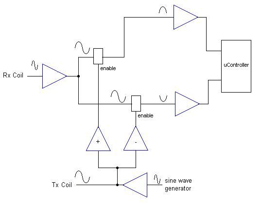
                I'm going to continue to work with the amplitude for now like Qiaozhi said I should. But I went ahead and drawn up a block diagram from reviewing the crazy ACE250 schematic. It looks like the TGSL schematic agrees with the basic design. I have to ask however...I don't see where the Rx waveform is compared to the Tx waveform to measure phaseshift. The Tx only gates on the positive and negative pieces of the Rx wave, but don't see anything calculating the phase. Where is the Rx phase relationship compared to the Tx?


                Comment


                • #68
                  EEG in general is not the best model for this. Typical EEG is low bandwidth (ten’s of Hz) small signal (ten’s of uV) system, subjected to very large common mode interference signals (powerline, usually) and CMRR is mandatory specification here (aside it must be floating, capable to survive defibrillator operation etc).

                  In MD requirements are somewhat different. First of all, you don’t need uV sensitivity as such, in best case you will have few mV coil disbalance signal and uV target signal imposed on it at operating frequency. Extremely high gain is not needed at input, actually it is below 100, gain is distributed. Most of the gain is provided by narrowband post-demodulator stages (usually called filters, but in most cases this is “second derivative” circuit, two differentiators defining motion response,or in some designs , true bandpass filters). Output of two channels, phase shifted to some degree relative to each other, is fed to comparator circuit producing target response. So, gain is distributed throughout entire circuit, not concentrated in front end. Using instrumentation amps with ridiculous gains is not good idea here, even high CMRR they can offer is not that critical.

                  Search for Tesoro and Fisher patents for simple description how phasing, gnd balancing, discrimination and this second derivative stuff is done, or analyze TGSL circuit more carefully.

                  Comment


                  • #69
                    Originally posted by Tepco View Post
                    EEG in general is not the best model for this. Typical EEG is low bandwidth (ten’s of Hz) small signal (ten’s of uV) system, subjected to very large common mode interference signals (powerline, usually) and CMRR is mandatory specification here (aside it must be floating, capable to survive defibrillator operation etc).

                    In MD requirements are somewhat different. First of all, you don’t need uV sensitivity as such, in best case you will have few mV coil disbalance signal and uV target signal imposed on it at operating frequency. Extremely high gain is not needed at input, actually it is below 100, gain is distributed. Most of the gain is provided by narrowband post-demodulator stages (usually called filters, but in most cases this is “second derivative” circuit, two differentiators defining motion response,or in some designs , true bandpass filters). Output of two channels, phase shifted to some degree relative to each other, is fed to comparator circuit producing target response. So, gain is distributed throughout entire circuit, not concentrated in front end. Using instrumentation amps with ridiculous gains is not good idea here, even high CMRR they can offer is not that critical.

                    Search for Tesoro and Fisher patents for simple description how phasing, gnd balancing, discrimination and this second derivative stuff is done, or analyze TGSL circuit more carefully.

                    Correct!
                    I also wandered why he want to "see" exact changes in microvolts there?
                    But than i thought; man must have some interesting idea and that's why i suggested use of precision instrumentation amplifier.
                    And how is usualy done; he can see in some eeg, for example.
                    But giving him such suggestion i also got some, yet "misty" idea of using precision instrumentation amplifier in another stage in metal detector!
                    Ha!
                    Will talk about this only if achieve something in my trial&error workshop!
                    Ciao!

                    Comment


                    • #70
                      "...I have to ask however...I don't see where the Rx waveform is compared to the Tx waveform to measure phaseshift. The Tx only gates on the positive and negative pieces of the Rx wave, but don't see anything calculating the phase. Where is the Rx phase relationship compared to the Tx?..."

                      Read something about synchronous demodulators for a start.
                      Regards!

                      Comment


                      • #71
                        Practically all nowadays designs are using synchronous detection to form a phase detector. Further on by comparing these "channels" you have selection of a single quadrant, hence discrimination of ferrous vs nonferrous, and some rare implementations show you signal phase to determine possible candidates for target metal.
                        VLF detectors are not immune to non-conductive materials' magnetic properties, so you'll hear a lot about "ground balance", which is nothing else than one of these channels phase. The idea is that every sinus signal multiplied by a signal in quadrature, which is cosine, is symmetrical against zero ... sin x * cos x = 1/2 sin 2x e.g. DC component equals zero. For every other phase it will not be zero.

                        Comment


                        • #72
                          Originally posted by Tepco View Post
                          ...First of all, you don’t need uV sensitivity as such, in best case you will have few mV coil disbalance signal and uV target signal imposed on it at operating frequency.
                          So far my experiments on the workbench are saying I do need uV sensitivity, unless there is some secret that I am not understanding.

                          Using the Volt Peak function on my o-scope, it gives me readings in millivolts. I can detect a coin about 4 cm away because I see the scope change by about 2 mV. If I am going to be able to detect coins 20-30cm away, it seems I certainly need to be able to detect a change in uV.

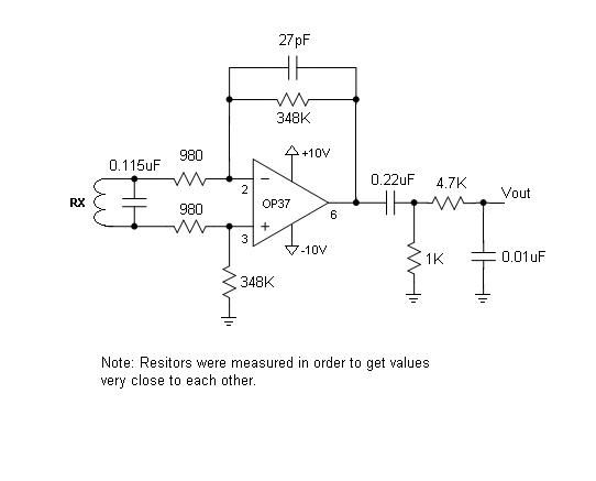
                          Here is my preamp circuit now which allows me to see a change in millivolts. But still not good enough.


                          Measuing Vout, it is normally about 1Vp-p with no coin around the ring.

                          Davor, I heard what you are saying, and understand all the words, but don't have a clue what it means. Maybe after a few sips of wine it will make sense.

                          Comment


                          • #73
                            Originally posted by JamesPicard View Post
                            ...Davor, I heard what you are saying, and understand all the words, but don't have a clue what it means. Maybe after a few sips of wine it will make sense.


                            You are not the only one! Join the club and take a glass!

                            Comment


                            • #74
                              Cheers

                              Comment


                              • #75
                                You are not looking for microvolt signals, you are looking for microvolt changes to millivolt signals, hence you don't need gains of 10's of thousands (that would simply saturate your amplifier) just a pre-amp gain of 50 to 200 would be typical, and enough. Your circuit seems to be higher gain, which may cause you trouble, depending on the supply voltages you end up using, and the coil's standing output voltage. If you intend using ADC's, the input voltage range of it/them may be a significant constraint. Using +/-2.5V supplies would be worth considering, feeding an ADC run off +2.5 and -2.5 rails. But other options exist.I would recommend reading a couple of Bruce Candy technical articles on Minelabs website, on the theme 'how do detectors work?', noting the way signal levels fall off with target distance (inverse 6th power rate eventually, still inverse 4th power when close). Plus they explain the demodulation function, ground signal effects,etc.

                                Comment

                                Working...
                                X