
 Tweet
Tweet
You're hand is conductive via salts. Probably shielding the coil will eliminate this.
-
-
The fact that you can detect your hand is a good sign, it shows you have the sensitivity high enough, now. It's probably true to say that if you had a coil designed for a high-end machine, rather than an ACE, you might get less 'hand-sensitivity', but even good detectors can display the effect. I was never sure how much was due to the 'salt-water' nature of the body, how much due to capacitance, and whether the iron content of the blood might also be a contributor.Comment
-
The coil shield should block the capacitive (proximity) effect, and sodium chloride in the body will act similar to detecting on wet sand at the beach; but I doubt that iron in the blood will cause any problem at all with a metal detector.Originally posted by Skippy View PostComment
-
I'm inclined to agree with you regarding the iron/blood possibility, I think even if it was detectable, it would probably be seen more like ferrite, and give such a small phase lag as to be 'undetectable'. Capacitance may be a real phenomenon on lower-end machines/coils, though James' coil would hopefully be good enough. In practice, hand sensitivity is a problem that can be lived with.Comment
-
It might also be worth checking that the coil is wired up correctly. For example, if the shield is not actually connected to the 0V rail, then unexpected things can happen.Comment
-
This coil doesn't have a shield. The connector just has 4 pins, 2 for TX and 2 for RX.
Comment
-
Are you still using the Garrett coil? If so, it will have a Faraday shield in the coil shell. There must also be a shield around the cable going to the detector, which will be connected to the Faraday shield. Check if any of the wires are connected to the cable shield. The bottom line is that you must make sure the cable shield (and therefore the Faraday shield) is connected to 0V.Originally posted by JamesPicard View PostComment
-
The ACE250 has a 5-pin connector. The shield is pin 5. This should be connected to pin1, and ideally to the outer case of the connector. The connector shell doesn't appear to be joined internally to the coil wiring. On the ACE250 main control box, pins 1,5 and the outer shell are all joined together on the PCB. Pin 1 is, I think, the oscillator ground (pin 4 oscillator hot), if there is a seperate shield for the recieve coil, it may be internally connected to one of the recieve coil wires (pins 2 or 3, not sure which).Comment
-
The Excelerator EQ2 coil does have a 5 pin connector to connect up to the ACE250. However, this coil is not using pin 5. How do I know? Because I cut off the connector and checked.
It was just 2 wires to pins 2,3 for Rx (1 shield around 1 solid) and 2 wires to pins 1,4 for Tx (1 shield around 1 solid). However, there was no outer shield around the whole thing that goes to pin 5.
Apparently its not needed since people who have ACE250 and buy the Excelerator coil love it, says it gets much better performance than the stock coil. I don't know though, since I don't have the ACE250....just simply trying to build my own.Comment
-
Now we're getting somewhere. Please can you confirm whether the two screens are electrically connected or not? If the answer is yes, then they must be connected together in the coil shell.Originally posted by JamesPicard View Post
Regardless of whether the answer to the above question is yes or no, do the following
1. Connect the TX wires with the TX shield going to 0V.
2. Connect the RX wires with the RX shield going to the inverting (-ve) input of the preamp and the RX wire going to the non-inverting (+ve) input, via the input resistors of course.Comment
-
ok, I verified. There is no connection between the shields of the tx and rx pair. So essentially there is no "shield" at all among these wires. Since the wires are all separated from each other with no connection between them in the coil....the shield portion of each cable acts simply as a wire. So essentially its 4 wires, 2 for the Rx and 2 for the Tx.
In my continuing quest to work on amplitude sensitivity right now, I have gone this route. Is it better, worse, same, well I don't know since I'm not a guru. But it does work. Don't have any experience in this area to draw from so maybe you guys can give me your thoughts. Here is the current design...
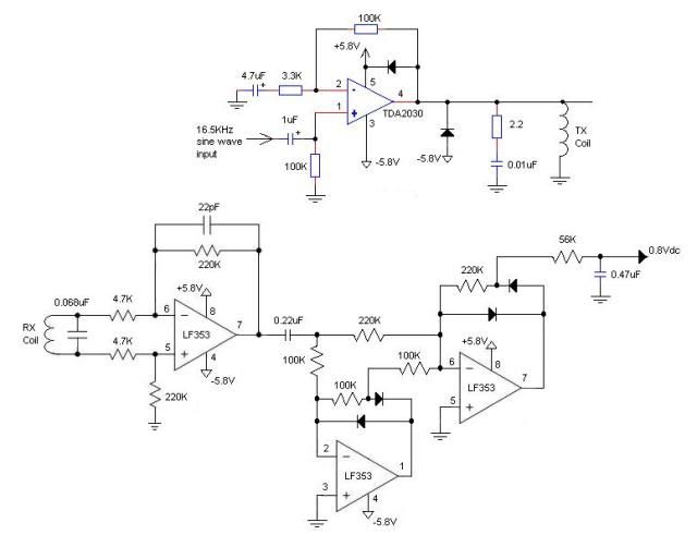
The last stage is a full wave "precision" peak detector. It takes the 16Khz rx signal and converts it to a peak dc voltage. When no metal is around the coil, it is 0.8Vdc (actually 0.780 Vdc). I am very happy in that it an extremely clean dc level at this point. I think I will run this signal now to summing amplifier that will offset the 0.8Vdc to 0V, then amplify the signal x50 to get an extremely sensitive detector for microvolt levels. At that point, I can use a ADC to "average" out the noise and look for the microvolt increases from small coins.
What are you guys thoughts on this? Maybe its possible I don't use the summing amp circuit, but immediately go right to the ADC?Comment
-
In better detectors, the loop cable uses dual coax for the TX and RX, with the coax shields being ground (or, possibly on the TX side, +V). In cheaper detectors, the cable is simple 4 or 5 wire with an overall shield. In dirt cheap detectors there is no cable shield, but there will be a loop housing shield. In any case, most likely either the TX ground or the RX ground is connected to the housing shield. Usually it's the RX ground. In sorryass-dirt-cheap detectors there is no housing shield, and the detector will false horribly in wet grass.Originally posted by JamesPicard View Post
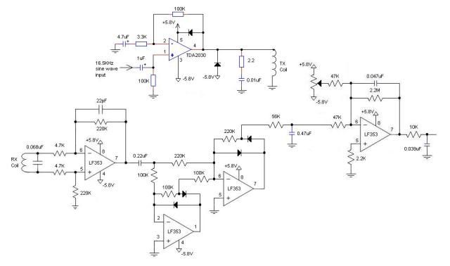
If you want to amplify x50, you will need to offset to 0v. However, the residual signal is due to coil imbalance and, even worse, ground signal (which you won't see on the bench) so I question how much you will get out of this. You may have to make the offset circuit use an autotune method, and look for rapid changes due to targets.The last stage is a full wave "precision" peak detector. It takes the 16Khz rx signal and converts it to a peak dc voltage. When no metal is around the coil, it is 0.8Vdc (actually 0.780 Vdc). I am very happy in that it an extremely clean dc level at this point. I think I will run this signal now to summing amplifier that will offset the 0.8Vdc to 0V, then amplify the signal x50 to get an extremely sensitive detector for microvolt levels. At that point, I can use a ADC to "average" out the noise and look for the microvolt increases from small coins.
What are you guys thoughts on this? Maybe its possible I don't use the summing amp circuit, but immediately go right to the ADC?
- CarlComment
-
Well, in layman's terms, I think you told me it won't be stable. Maybe that's what I'm seeing now....on the bench, the output from the summing amp drifts around in terms of seconds...drifts about +/- 15 mV every 5 - 10 seconds. Drives me nuts, although I guess I can just look for sudden changes only in software and not pay attention to this drifting. But it does add a level of complexity that I'd rather not have to deal with.
Anyone have any suggestions to over come this slow drifting for the summing amp circuit? (Edit: Actually, its not really a drift, it basically will jump +-10mV every few seconds....then hold for about 5 - 10 seconds....then jump suddenly again +-10mV...then hold for awhile....just keeps repeating that which will make it hard to overcome in software).
Comment
-
"...Actually, its not really a drift, it basically will jump +-10mV every few seconds....then hold for about 5 - 10 seconds....then jump suddenly again +-10mV...then hold for awhile....just keeps repeating that which will make it hard to overcome in software..."
Disconnect coil and check again if there are still those "jumps".Comment
-
Originally posted by JamesPicard View Post
This circuit looks more like “industrial” detector, some of them are built using similar topology, not like something intended for normal metal detecting. If you make motion detector, no offsetting is needed, you can add AC coupled stage (differentiator or filter) and use as much gain as you need, but still you will have some disadvantages using this circuit:- This is absolute metal detector, no discrimination is possible this way, you can detect very small, microvolt changes in coil signal, but phase information is lost in rectification process.
- No ability to provide ground compensation, so no matter how sensitive this circuit can be, will be more or less (probably completely) useless in any soil and achieve its full sensitivity only in air.
Comment
Comment