Announcement

Collapse
No announcement yet.

Ground balance add on board for Mini pulse .

Collapse
X
 
  • Filter
  • Time
  • Show
Clear All
new posts

  • Ground balance add on board for Mini pulse .

    Hi
    I have been trying to make a add on board for Ground balance on the MPP.

    Ive copied what Digger429 did with his ground balance circuit and have made a test pwb.


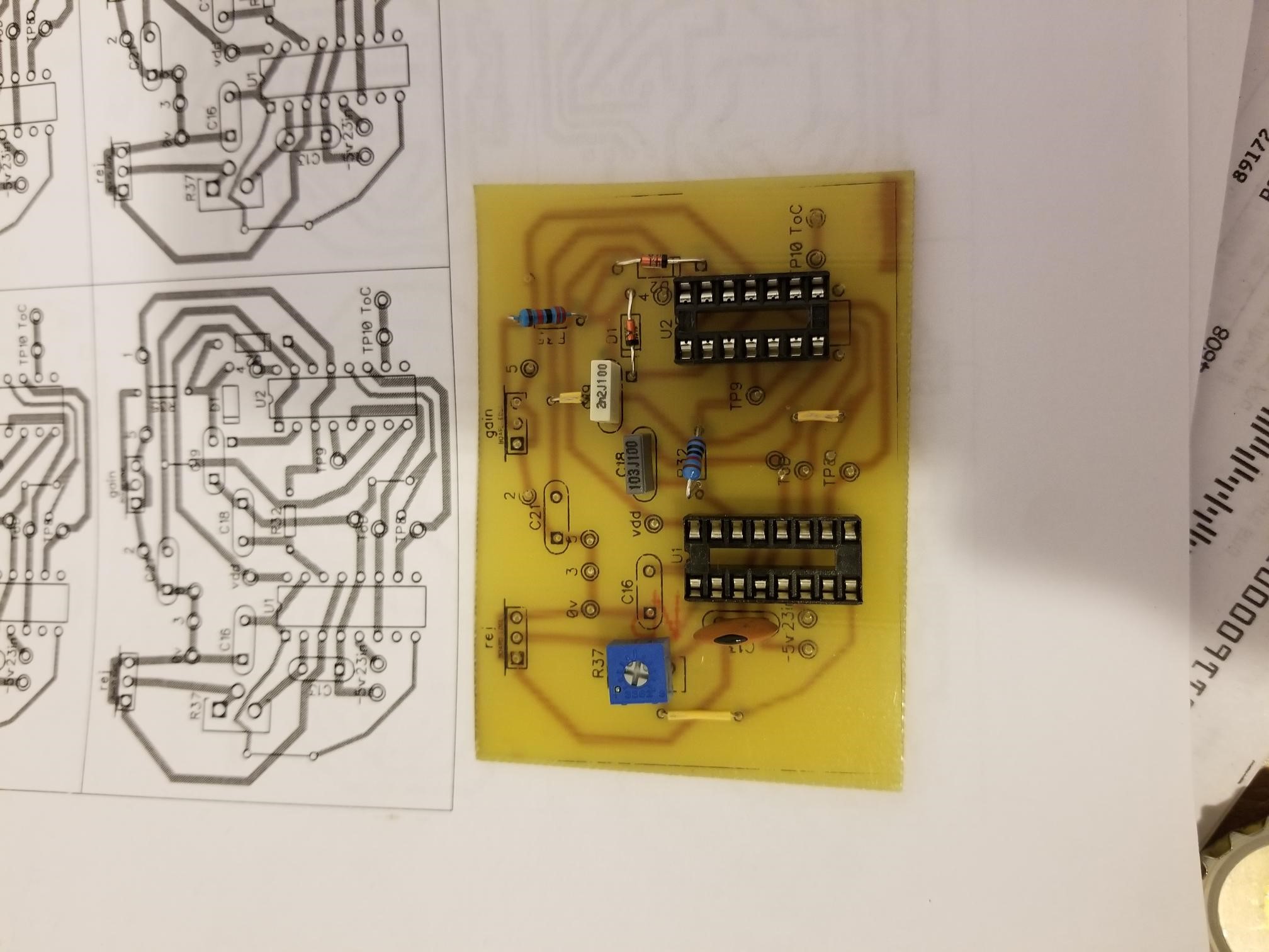
    This one is for the rev e beach but with a legend change can also work for the rev d.

    My thoughts are to make it switchable for when its really needed.

    Ive have read in many posts that Davor designed a Ground balance board in the same manner.

    Does any one know what this thread is under?
    I have been searching for a while and cannot find it.

    I would like to review his design hoping to maybe reduce the circuit before going too much further with my current board.

    Thank you all.

    P.S Merry Christmas
    Attached Files

  • #2
    I found Davors circuit in the original MPP thread.
    Looks like a pwb was not created but all the info is there.
    Im going to have study the thread more as there are allot of changes, so for now i thnk I will just continue with the stock MPP sampler.
    Thanks Again

    Comment


    • #3
      Originally posted by godigit1 View Post
      I found Davors circuit in the original MPP thread.
      Looks like a pwb was not created but all the info is there.
      Im going to have study the thread more as there are allot of changes, so for now i thnk I will just continue with the stock MPP sampler.
      Thanks Again
      Please post a link to that thread please. This makes it easy for us to follow what you are looking at.

      Comment


      • #4
        Hi waltr,
        http://www.geotech1.com/forums/showt...se-Plus/page17
        Post 403 is the circuit Davor designed.
        Thanks
        .

        Comment


        • #5
          Thanks.
          That is the "3 sample" method of GEB using hardwared circuits for timing.
          I use this 3 sample method in my HH but use a micro-controller for the timing.
          This method does work.
          Se my thread here for more info:
          http://www.geotech1.com/forums/showthread.php?24251-My-take-on-the-HH2


          Please post additional pictures and results.

          Comment


          • #6
            I was just drawing this up to do the same thing.. After looking at digger429's drawing had some question on a couple of his wiring.
            I'll edit the pic so it's easier to answer here shortly.

            Are the pots in green circles front panel?
            Is the connection in blue circle to 5v or -5 and is it a trimmer?
            Is the one in red circle a trimmer?

            Click image for larger version

Name:	oYFuQwz.png
Views:	1
Size:	661.5 KB
ID:	352635
            Last edited by geoscash1; 12-27-2018, 02:46 AM. Reason: Image

            Comment


            • #7
              try and get the 4011 working and to trigger first , they need everything working at 100% to trigger. I made Davors cct. but did not put it into MPP.

              Comment


              • #8
                Originally posted by 6666 View Post
                try and get the 4011 working and to trigger first , they need everything working at 100% to trigger. I made Davors cct. but did not put it into MPP.
                You lost me 6666, What 4011 ??? ... the mpp doesn't have a 4011 nor does the GB circuit from digger429 that is being used here.

                My questions still stand as far as a couple of digger429's connections on his schematic, cant tell if they are just resistors to -5v or if they are supposed to be trimmers, also the pot after/around the 22k resistor, I think that 22k can be eliminated and a 50k panel pot used in that position but I could be wrong.

                I want to work digger429's circuit into the mmp full schematic that way I can just have a board made with all components on it instead of using an addon board. I love my mpp but it is terrible in hot ground so am hoping this may help it out a bit even if losing some depth/sensitivity. I have the circuit drawn up but want to make sure of a few of his connections before doing a board for it.

                Comment


                • #9
                  Thanks waltr,
                  Ill look at your build beeen thinking about using pics but im not code savy.
                  I actually have a Hammerhead timing circuit allready built for another project i may revisite my hammerhead after this Mpp build. Also have a chance and cuda to do so will be busy.
                  Thanks for your project.

                  Comment


                  • #10
                    Hi Geoscash1.
                    Im really not sure about what Digger 429 had going. Its kinda vague( hopefully he will chime in) but what I was doing was for the rev e beach. Basically i copied the whole pulse generator and was going to figure things out from there.
                    I have reject and gain on my board but they can be panel mounted , r37 or r6 for the rev d is on board.
                    So the green at r6 is on board then you have your reject pot that would be pl 3 on the scematic. I have added this to my piggy back board I dont know if I will really need it or not.
                    Im assuming the lower green circled pot is what is on the rev e scema as the gain pot. I added this also on my board but all can be wired to the panel if necessary. Im not totally sure but I think digger was using dual gang pots for these.
                    Looking at the rev e scematic may help figure things out.
                    The blue and red circles are where he connected the new transistors on the back of his board Im not sure if he just drew them wrong or he actually has pots there.
                    I figured I would get my board running and then add the pots if needed to do any fine tuning and then do a final pwb design.
                    I have to revisite his post and refresh myself before going too much further.
                    I hope Ive helped im a little confused about that as well .

                    Comment


                    • #11
                      Geoscash 1,
                      Digger 429 wrote
                      I also put a dual gang potentiometer for the outputs that go to C and D to control the ground balance strength. With field testing I think I'll throw that out and just put a switch, because the potentiometer at R11 does the same job.

                      So no pots at c and d I think, this is also where I wanted to add a switch to turn gb on or off when needed.

                      Comment


                      • #12
                        Originally posted by godigit1 View Post
                        Hi Geoscash1.
                        Im really not sure about what Digger 429 had going. Its kinda vague( hopefully he will chime in) but what I was doing was for the rev e beach. Basically i copied the whole pulse generator and was going to figure things out from there.
                        I have reject and gain on my board but they can be panel mounted , r37 or r6 for the rev d is on board.
                        So the green at r6 is on board then you have your reject pot that would be pl 3 on the scematic. I have added this to my piggy back board I dont know if I will really need it or not.
                        Im assuming the lower green circled pot is what is on the rev e scema as the gain pot. I added this also on my board but all can be wired to the panel if necessary. Im not totally sure but I think digger was using dual gang pots for these.
                        Looking at the rev e scematic may help figure things out.
                        The blue and red circles are where he connected the new transistors on the back of his board Im not sure if he just drew them wrong or he actually has pots there.
                        I figured I would get my board running and then add the pots if needed to do any fine tuning and then do a final pwb design.
                        I have to revisite his post and refresh myself before going too much further.
                        I hope Ive helped im a little confused about that as well .
                        Hey thanks for the reply godigit....

                        Ok, that makes sense.. I guess I should have went back and reread what he wrote in his first post.. got to busy staring at the drawings...

                        So, went back and read everything. I kinda just redrew what he had but added his ideas and changes for more clarity for myself. I removed the schematic references numbers on the changed parts and added the IC mc14538's as (U8-a/b and U9-a/b respectively to keep them in an orderly fashion) new parts. Attached is how I did it and will be adding it to my mpp. The only thing I kinda dont understand is how would you add a switch to turn off the GB when there are going to be GB-C and GB-D 2 (sets of wires) unless of course you add a switch for each but how and where would it be best to do that or put it in?

                        Here is what I did to it with Digger429's changes added to try out. I just need to figure out how to add a switch to be able to turn it on/off.
                        Click image for larger version

Name:	GB circuit for mpp.jpg
Views:	1
Size:	161.3 KB
ID:	352637
                        Click image for larger version

Name:	MPP GB Addon Revised 1.jpg
Views:	1
Size:	112.6 KB
ID:	352638
                        Attached Files

                        Comment


                        • #13
                          Disregard that last "on off switch" attachment, it is incorrect. I deleted it but somehow its still showing.

                          Comment


                          • #14
                            I was thinking a two pole switch on lines c and d to completly cut off c and d transistors.
                            But this leaves the timing active??
                            Im was also thinking maybe just a switch at -VG but i was going to try to play with that.
                            Im not sure if the circutry needs isolated so as not to effect the regular timing
                            Or if left running would effect the regular operation.
                            Seems like completly killing the signal would be a good option as it would also consume less power.

                            Your way ahead of me as far as having a good direction with your build and thank you beacuse you have made me re-think things a bit.

                            I have to go to Santa Cruze for a couple weeks on the first so I wont be able to finish for a while.
                            Ill have time there to work on a pwb though so i will make a piggy with your scematic for the Rev D.
                            Are you going to make a whole new pwb Or add components to you existing pwb ?
                            You had stated you did not want a piggy back board. so i was curious. If your making a new pwb I would go in halves or better on a pwb order.
                            Just Thinhing.

                            Comment


                            • #15
                              Originally posted by godigit1 View Post
                              I was thinking a two pole switch on lines c and d to completly cut off c and d transistors.
                              But this leaves the timing active??
                              Im was also thinking maybe just a switch at -VG but i was going to try to play with that.
                              Im not sure if the circutry needs isolated so as not to effect the regular timing
                              Or if left running would effect the regular operation.
                              Seems like completly killing the signal would be a good option as it would also consume less power.
                              By the way, thank you for posting this, I like what you did with your addon board, that helped a lot.. That should work nice.

                              You are thinking exactly the same thing I am. I am really unsure of exactly how to do it.. I had also thought, maybe a logarithmic on/off pot at the R11 but am not sure if that will disco the C & D lines and leave the original portion of the circuit working the way its supposed to either. I'm just not an engineer (well, maybe a garage engineer... lol) so really don't have enough smarts to know what will let the primary circuit work the way its supposed to and shut off the addon portion without screwing anything else up.

                              Yeah, I was thinking to just add Digger429's design right into the mpp revD schematic, it just seems it would make more sense to me and would make it easier for anyone new to building one. Instead of trying to fit another board or have another separated board for troubleshooting in case of issues, just have everything all on the mpp board. I really like my mpp but as mentioned it isn't so good on hot ground so if this will give it a better chance even with some depth loss, I'll take it.

                              I would love to do some boards with the GB added on but someone would have to take the hand kludged schematic and make new files. If someone is willing to do that, then you bet, I will do a board order no problem and do an order for as many as everyone may want and any help with funding would be fine with me..

                              Here is what I did to it so far, but this is by no means a working schematic, I just redid Digger429's circuit images and drew them into the mmp schematic with all of the changes to the parts, it would have to be checked over and redrawn with new reference for R components, C components and Q components in the addons sections.
                              Click image for larger version

Name:	MPP Revised with Ground balance.jpg
Views:	1
Size:	403.2 KB
ID:	352645

                              Comment

                              Working...
                              X