Announcement

Collapse
No announcement yet.

Re: Sensor ...

Collapse
X
 
  • Filter
  • Time
  • Show
Clear All
new posts

  • Re: Sensor ...

    Well, the things that u provided will be of good help but still there are some queries to be made.

    1. How much efficient is the preamplifier stage of the circuit shown by Phils

    2. Will the same circuit work if we will be able to tune it to the desired frequency...

    3. About the sensors how much the properties of both the sensors can differ in terms of number of turns till we get the Green Light

    4. Well finally i am able to get the bottles of the same dia i.e. 1 3/8 inches but i dont know about what would be the shape of the signal that i will get... Kindly provide some reference. with respect to pakistan.

    5. Now about the tunning of the sensors if we connect the sensors in a differential configuration and apply some frequency to the nearly placed Solenoid coil What applitude do i get to feed it in the soundcard or what is the Signal levels and frequency ranges of the soundcard to be fed.

    6. and Any particular specification of the solenoid coil to which we apply some frequency.

    7. We have the sensor setup as shown by phils you suggest any cable to be extended from the sensor to the amplifier ...

    8. if the sound card can pick up the signal then can we directly feed the differential signal of the magneto meter with the sound card in order to develop a software base approach ..
    if not then please provide suitable amplifier to amplify the signal to be interfaced with the soundcard

    9. What if we want to check it using Analog Oscilloscope guide me with the procedure ...

    10. The sound card is not available to us cause of restriction in my institution. but pass me the software to find the FFT/ Spectrum of the signal by sound card so i try to arrange the sound card ...

  • #2
    Re: Sensor ...

    I am currently in relation with a student named Salman Masood also from Pakistan and it seems to me that his questions about MAG building are very much like the ones you ask yourself.

    Do you happen to know him? Are you from the same school?


    Now for the answers to your questions:

    I do not know exactly what is the performance of the Phil’s pre-amp stage but it looks like a standard low noise, transistor-oriented stage.
    Since the pre-amp stage is broadband, I do not see why there should be any problem if you tune the sensor. The tuned frequencies that will be amplified will be fed with a higher amplitude than the out of band frequencies.
    If you want to use two sensors for a differential mag configuration or for noise canceling on a global field mag, you need to make them reasonably identical in terms of resistance and inductance (same wire, same internal diameter, same number of turns).
    The shape of the signal will always be a sine wave with a level (as low as possible) of white noise. The shape or the frequency of the signal do not depend on the shape of the sensors. Its frequency only depends on the local magnetic field value. However, the RMS amplitude of the sine wave depends on the quantity and type of liquid in the bottle, the polarization current, the number of turns…
    There are two methods to tune the sensors;
    Feed the coil directly with an AF generator and measure the FFT peaks there too. In that case, you feed the sensors with a signal around 100 or 200mV RMS, that’s enough. Do not go over these values otherwise you will get to the maximum PCM values of the sound card and the signal will be cut and then, will look like a square wave and not a sine wave.
    Indirectly feed the sensor with AF frequencies through the use of an auxiliary coil placed close to the sensors to be tuned. In this case, you adjust the level of the fed AF signal until you get a measurable signal on the sensors.
    In both cases, vary the frequencies from 500 to 4000Hz by steps of 500Hz and note the heights of the FFT peaks. The tuned frequency is at the maximum peak.

    In the indirect feeding method, make a small coil of around 8cm diameter and 100 to 200 turns of thin wire. In the direct feeding method, put a 100 to 200 ohms resistance in series with the coils to be tuned to protect the AF generator.
    50 ohms coax or low noise microphone shielded cable (with a thick wire) or RG-8 Mini coax cable
    If the amplified signal is more than 50-100mV RMS, you should be able to feed an audio card with it. It just depends on the global gain that you make on the stages of amplification.
    An oscilloscope would just show you a sine wave signal mixed with noise. This would not give you any useful information.
    The Spectrum Lab program able to calculate and display FFT bins is using a PC sound card. This is a must. This is the link to that program: http://www.qsl.net/dl4yhf


    Good luck,

    Willy

    Comment


    • #3
      Re: Sensor ...

      Dear Willy,
      The testing and calibaration of the sensor with the method that you have passed on to me is done and I have got the capacitance(700nf) on which they are giving the maximum amplitude.
      I first placed the coil near one of the coil connected in differential configuration and then near the other one both of them are giving the same response. I am interested in the theory of this testing as well if u can guide me.
      Now the testing is been done and the capacitance value is matched now I am interested in the Amplifier Your Help is very much appriciated.
      Now about the amplifier design I would like to interface the sensor signal to the soundcard and i can develop the software to access the sound card but the problems are to design an amplifier that could enable me to amplify the signal to the sound card input amplitude level.
      Will the circuit of the phill at any stage will be useful to aquire the signal. if yess then at which point? ... The occiloscope is not responding well to the minute signals. So unable to see the signal...
      An amplifier design is needed which can amplify the signal to the Soundcard level.
      and one thing more and that is the testing of the differential Magnetometer must not be made inside the building as there are many chances of noise as quoted by Phil. Then how to test the circuit. Can I place the sensor away from the building and use the cable that u have mensioned to connect to the circuit and test it inside the building ...

      Comment


      • #4
        Re: Sensor ...

        At which frequency did you get the maximum amplitude? It should be around 1600Hz in your region. How did you measure the RMS amplitude of the induced sine wave signal?
        In principle, the amplifier design of Phil is more than sufficient in gain to feed the microphone input of an audio card with the resulting signal.However, the sound caard itself will only perform the necessary ADC but NOT the FFT calculation. You will need to use a program like the SPectrum Lab or an FFT library to calculate the FFT bins.
        An Oscilloscope is perfectly useless in this case. The raw input signal is much too small and the amplified signal is mixed with thermal and local noise.
        You can indeed put the sensors outside of a building (far from iron and electrical cables) and connect them to the electronic box in the lab using a long shielded cable (it better have a low resistance and low noise pick-up in that case). You should also review the tuning of your sensors since the cable will add up significant capacitance to the whole system.

        Willy

        Comment


        • #5
          Re: Sensor ... (CORRECTION)

          CORRECTION
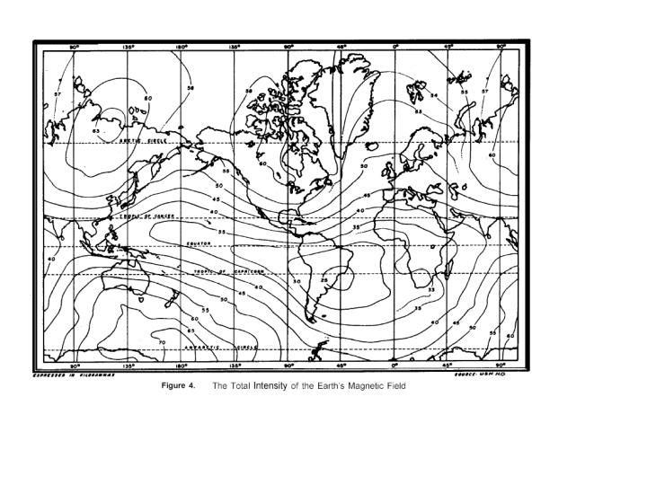
          The precession frequency in your region is 1916Hz and NOT 1600Hz.

          Willy

          Comment


          • #6
            Re: Sensor ...

            The value of the tuning capacitor (700nF) is a bit surprising. It looks to me on the high side. Are you sure that you located the FIRST amplitude peak at 1900Hz?

            Willy

            Comment


            • #7
              Re: Sensor ...

              sir plz confirm again the precession frequency in our region.is it 1916hz.how u have calculated.

              Comment


              • #8
                Re: Sensor ...

                plz again explain the procedure for the sensors using spectral lab program.tell us about the RMS values of the sine wave in detail.

                Comment


                • #9
                  Re: Sensor ...


                  From this map graduated in xx,000 Gammas.

                  Willy

                  Comment


                  • #10
                    Re: Sensor ...

                    Connect an AF generator to the coils (NO TUNING CAPACITOR) through a resistance. Connect the audio input (line connector) of the audio card to the coils. Run the spectrum Lab program and start the AF generator at 500Hz. You should see a single FFT peak on the screen at 500Hz. Adjust the RMS amplitude of the AF generator to get 100mV at the coils level. Keep this adjustment constant from now on. Step up the frequency by 500Hz and measure the FFT peak height, note it. Continue until you get to 4000Hz. The frequency for which the FFT peak is maximum is the self-resonant frequency of the coil system with its internal capacitance and inductance. You should get a frequency that is too high. In order to lower it to the required value, you should put a capacitor value in parallel with the two coils in series. Redo the complete process and note the frequency of the peak. Adjust the capacitor value until you get the required frequency.
                    Willy

                    Comment

                    Working...