Announcement

Collapse
No announcement yet.

Barracuda circuit.....

Collapse
X
 
  • Filter
  • Time
  • Show
Clear All
new posts

  • Barracuda circuit.....


    Hi

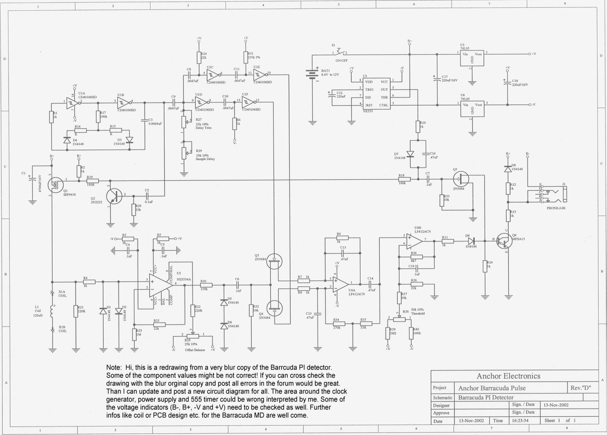
    this is a redrawing from a very blur copy of the Baraccuda PI. If you are interested you can cross check the diagram and post the errors in this forum. Please read the note in the schematic.

    thank's in advance....Chris

  • #2
    Re: Barracuda circuit.....

    Here is what I have, from an older board:

    R1 - 100k
    R6 - 33k
    R11 - 22k
    R12 - 33
    R13 - 100
    R14 - 0
    R15 - 150k
    R16 - 100k
    R17 - 6.8k
    R18 - 39k
    R21 - 330
    R22 - 270k
    R23 - 1k
    R24 - 150k
    R25 - 1M
    R26 - 1k
    R27 - 20k
    R28 - 20k
    R29 - 25k (?)
    R31 - 33k
    R33 - 2.2M
    R34 - 100k
    R35 - 270k
    R36 - 100k
    R39 - 33k
    R40 - 27.4k

    C7 - 100p
    C17, C18 - 220u/25v
    C19 - 0.1u

    Q1 - TIP127 (Darlington PNP)
    Q3, Q4 - 2N5485

    7660 - pin 8 to B+, pin 6 N/C

    Everything else matches. I'm sure there have been component tweaks over the years, so other boards may vary.

    - Carl

    Comment


    • #3
      Re: Barracuda circuit.....

      Oops... Pawel caught another one... swap the inputs on U4a.

      - Carl

      Comment


      • #4
        Re: Barracuda circuit.....

        Hi Carl

        thanks for your kind support. Now it's a difficult task to adopt (some of) your component values. Because the board you mention is an older version of the Barracuda. I'm pretty sure that yours is an earlier version than Revision "D" because of Q1 (TIP127).
        Why? If I would be the designer I would try first a PNP Darlington and in a redesign I would change it to a Power MosFet. I wouldn't do it the other way round. Ha Ha... and another thing confuse me where is the 7660? In the drawing is a 555 timer. Or am I wrong?
        The input pins of U4a are correct drawn according the blur copy.
        Is it in the original copy wrong?

        Regards
        Chris

        Comment


        • #5
          Re: Barracuda circuit.....

          Hi Chris,

          1. Q1: You have used IRF9410 - but it is an N-channel MOSFET. It should be an irf9530 (a P-channel one).

          2. 7660: Yes, there is a 555 in the drawing - but this is an error. It will never work. Perhaps in a very early version a 555-based voltage inverter was used and somebody forgot to change the chip in the schematic. This is an almost correctly wired 7660 switched-capacitor voltage converter.

          3. U4a: Next evident error in the "original". You should expect more bugs.

          4. Lfe is brutal.

          Regards,

          Pawel

          Comment


          • #6
            Re: Barracuda circuit.....

            5. Bug in point nr 4. Correct version:

            4. Life is brutal

            (quod erat demonstrandum)

            Regards,

            Pawel

            Comment


            • #7
              Re: Barracuda circuit.....

              Hi Carl & Pawel

              Thanks for your support. I'll wait till the weekend and collect error messages. Maybe more are coming. On Monday I'll post an update of the schematic with all collected errors.

              Regards
              Chris

              Comment


              • #8
                Coil Resistance

                I think the coil measured 129 ohm's ?

                Comment


                • #9
                  Coil Resistance mistake

                  It should have been more like 1.29 ohms, not 129 ohms.

                  Comment

                  Working...