
 Tweet
Tweet
schematic
-
-
all information on a site of author http://radiodom.ucoz.ru/index/selekt...ot_m_quot/0-14
video http://depositfiles.com/files/fjxclgtbx -
Some technical data (regarding author):Originally posted by kt315 View Post
- IB type detector,
- working frequency selectable from 4 to 12 kHz (coil have to be tunned to selected Freq.)
- multi-tone ID
- supply 7-9V
- consumption 50mA
- discriminative
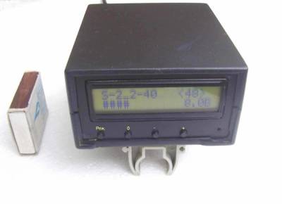
- visual display
- suggested/tested coil 20cm (CC type with RX and TX coil tunned in resonance)
- sensitivity in air test: 25mm (1") coin at 30cm (12") distanceComment
-
Hi
Anyone here built this detector ?
The circuit Ive posted uses a MC34119, cheapest price I can find is £15.00, MCP601 is only £3.53, got everything else in stock.
Looked at a video file on the site and either it doesn't do it justice or theres instability problems and needs further work.
Would help if I could understand Russian.
RegardsComment
-
It seems there is no means for measuring TX phase to use as reference. If the TX tank is anywhere near its resonance, where it's reasonably efficient to drive, shifts in its inductance due to ground conditions will shift the TX phase, regardless of fixed tx drive. Air tests would likely not reveal this?Comment
-
Anyone here attach the PCB please, or PM-me,because on the author's site there is no PCB Plate
thanksComment
-
Which size is the PCB plate for printing??? in cm or inches...
thanksComment
-
you can find the right printing sizes if you take the atmega ic socket for controll the scale
or the pi n connector for lcd most 2,54mm distance pin to pinComment
-
I did give a direct link on LAY file. let him upload SPRINT LAYOUT 6 from the net and in the soft he can measure what he want easely.Comment
-
I built this scheme. It is practically the same and it does not work, I think my connections to lcd are wrong. The detector makes noise when I press a button and the LCD is illuminated 3 seconds and no letters.
pcb file upload I have used, do not hold me responsible if inoperative.
If anyone can help I would appreciate.
Pcb.pdfComment
-
-
Originally posted by The-Force View Post
Thank you very much. Modificare the circuit right now, tomorrow I comment. Thank you very much again.Comment
-
It did not work, I'll build another from 0. Spoiled several integrated or maybe the lcd.
The-Force which is the pcb of your circuit?
Image A or B?
Comment
-
your 7805 smd regulator gives enough power for circuit and lcd Display?Comment
Comment