
 Tweet
Tweet
Hello, I am a new to metal detecting. A few months ago I bought a relatively inexpensive Shaper Image Express metal detector for using on my local beaches. Mostly I like walking along the sea shore and thought that picking up a few coins along the way might be fun. As it turns out, I have already found 1 gold wedding ring, 2 silver rings and enough change to pretty-much pay for the units purchase price.
Needless to say I am hooked!
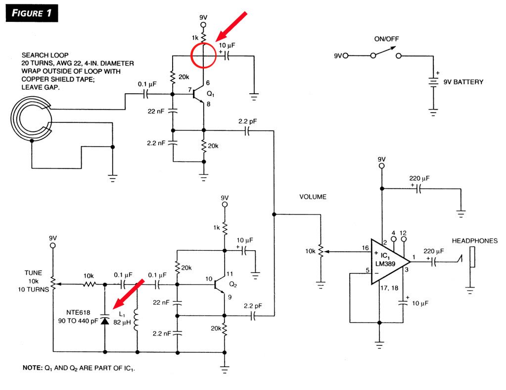
Anyway I decided I wanted to learn better how metal detectors work so I decided to build one. I looked around the internet and found the Hageman BFO schematic and thought it was simple enough that even I could build one.
http://www.geotech1.com/pages/metdet/projects/edn/edn.pdf
But I am having trouble getting it to do anything.
My question is this, has anyone on this forum ever build one of these BFO’s and if so, is there any tricks to getting it working?
Thanks!
Needless to say I am hooked!
Anyway I decided I wanted to learn better how metal detectors work so I decided to build one. I looked around the internet and found the Hageman BFO schematic and thought it was simple enough that even I could build one.
http://www.geotech1.com/pages/metdet/projects/edn/edn.pdf
But I am having trouble getting it to do anything.
My question is this, has anyone on this forum ever build one of these BFO’s and if so, is there any tricks to getting it working?
Thanks!


 ) but I want to make the search coil larger then 4 inches because my steps are longer then 4 inches. Around where I do most of my detecting, 6 inches into the dry sand is deep enough. Anything deeper then that is usually an old beer can.
Comment