If this is your first visit, be sure to
check out the FAQ by clicking the
link above. You may have to register
before you can post: click the register link above to proceed. To start viewing messages,
select the forum that you want to visit from the selection below.
OK I understand, but I do not think you can have 8-9V~ on TX.
Measuring with coil and you'll have a surprise.
Regards
Ofcourse with coil should be about 5 volt's.
I'm just measured on this way for pcb testing. If i dont get 8 volt's without coil, something is wrong, right?
I don't see any problem by testing pcb on this method.
Regards
Good evening, I ask for your help.
On a pcb silverdog, which I just realized.
Has the power on, it emits a long and continuous sound ... coil plugged or not .... I do not know how to find the breakdown ... thank you for your help ..
Hi, i have pic16f88 i/p i couldn't programmed by allpicprog and this JDM https://www.youtube.com/watch?v=8qznzP6M2ys
it detect my pic sometimes but i cant burn it, any solution..
I would like to add a contribution to the idx-pro with a new VDI firmware. This is not for replacing holyuser's firmware which works very well but to have an alternative firmware for testing. I programmed it myself from scratch in C and it works with the fisrt PCB layout using the MPC602 op-amp (the TL072 probably won't work well).
It does the following: first it waits for a trigger signal: x and/or y above a given threshold (trigger level). Once there is a trigger, e.g. the search coil is near to a metal it takes measurements of (x,y) for ~400ms and selects the maximum x with its corresponding y value (thus x is always greater than zero and similar for the same target), transforms (x,y) to polar coordinates (rho,phi) and displays the result until there is a new trigger.
With this simple approach, I was able to go above 70% using a Don Bowers' coil and with small power consumption (~2.6 mA without back-light). This is similar or better than the reports for the arduino, but without the need of an extra battery pack which makes the arduino not a very good option for this.
You can choose to display the rho coordinate (I called it STR from strength), the VDI name and/or the (x,y) coordinates e.g. for debugging. I also add an option to exclude the 3rd quadrant in the VDI (i.e. x and y both negative) to avoid a sign inversion that occurs when selecting the maximum x value (-90,180). But you can use the default, i.e. from -180 to 180.
The strength of the signal (STR) is related to the depth/size of the target, i.e. small and deep targets have small STR values, and big and shallow targets have large STR values. Although the VDI values depend on the alloy, size and thickness of the target I found these intervals with a Bowers' coil:
Maybe someone would like to test it with different metals, coils and find a more generic ranges and/or a correlation with the strength to improve the identification...
Adjust the contrast trimpot to see the characters in the LCD
Find the "ADC offset" or virtual ground for your PCB (e.g. mine is 2.49V):
Select "ADC offset" from "Display options"
Wait until the readings stabilize having the coil away from any metal and RF
Press ENTER/NEXT button an enter this value in the "ADC offset" menu
Save the changes
Find the lowest trigger level: the lower the higher sensitivity
Adjust the RT2 to have similar VDI numbers: wave a small foil above the coil and adjust the trimmer until it reads ~0 (within +-2 degrees)
Optionally adjust the battery voltmeter displayed at the top right of the LCD: with a multimeter measure your battery voltage and increase/decrease the voltage in the config menu until they match. This is necessary to take into account R1 and R2 values, similarly with the different components for the ADC offset.
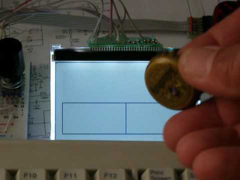
Here there are some pictures and the firmware files for the PIC16F88 and PIC16F690:
are you going to make the source available? Surely would be nice.
I'd like to port it to a different chip than the PIC16 family, as well as add a realtime counter. When going out during your lunch hour at work, I'd like to be able to set a time into the counter so when it counts down to 0, you know it is time to pack it in.....
.....
no problem, the source code is released under the GPL license (attached below) and it compiles with MPLAB XC8. To port the code to a different PIC you would only need to change the files mcu.h and mcu.c as in the directory P690 for PIC16F690. If you use the XC8 compiler in free mode you would also need to remove some features in order not to exceed the space in the PIC and if you have a gitlab account you might access the git repository at https://gitlab.com/eserradi/VDI.git for changes in the code...
 Tweet
Tweet


Comment