If this is your first visit, be sure to
check out the FAQ by clicking the
link above. You may have to register
before you can post: click the register link above to proceed. To start viewing messages,
select the forum that you want to visit from the selection below.
For soils that are non-conductive but have constant magnetic susceptibility. This would be a soil, sand, or rock whose grain size is above the SPM threshold. i.e. California black sand. Yoga Das states in the second paper, Section 3.1 and Observation 5
“Hence for measurements taken at times, t > 0, which is the case in pulsed induction detectors there would be no contribution from the soil. Thus, in theory at least, such soils would not affect the performance of pulsed induction detectors”.
In some special cases this is not entirely true as detection range can be affected by distortion and flux spreading in a strongly susceptible medium. I have known cases where the detection range was less than an “in air” test, and other cases where it was more. At no time though did the ground itself give a signal and there was no need for GB.
For non-conductive soils with frequency dependant susceptibility, i.e. that have a percentage of SPM grains, it is a different story. Section 3.2 Observation 2.
"From Equations 29-31, it is clear that unlike in the case of constant susceptibility soil, the transient signal due to magnetically viscous soil will persist long after the turning off of the transmitter current pulse and may be confused as signal produced by a buried metal object".
Moodz, there is no secret in "ASinc ringing".
I posted in the forum the circuit diagram of a ringing TX with the simplest pulse forming network. It is realized before more than 100 years.
You can calculate the components of the attached equivalent circuit diagram. Here is a calculator:
Thanks for all this info, its very interesting. But what can you tell us about what happens when you DO need to go below 10us which from what I've gathered is the case for a tiny nugget detector. Also do you have any more specific links to these 'various techniques' of which you speak for getting the delay down?
Thanks for all this info, its very interesting. But what can you tell us about what happens when you DO need to go below 10us which from what I've gathered is the case for a tiny nugget detector. Also do you have any more specific links to these 'various techniques' of which you speak for getting the delay down?
Cheers
Midas
Getting down to 5uS delay is not too difficult. The following steps need to be followed -
Make the coil with as low a self capacitance as possible, by using Teflon insulated wire; minimum cable to electronics, and maybe reduce the inductance to 200uH. Shielding is absolutely necessary and should be spaced away from the winding by Teflon spiral cable wrap. Moodz bifilar CT coil looks good for this use as the TX can be 100uH effectively and the RX 400uH. I have not yet had a fully working detector using this yet though.
Use a lower pulse amplitude but pulse more often. Say 0.5A peak at 10,000 pulses per sec. You can then use higher resistance (thinner wire, 30AWG) and some series resistance that will lower the coil TC.
Increase integrator and filter TC's to accomodate the higher sampling rate and still get an adequate response time from the rest of the amplifier/filter chain.
Bear in mind the the viscous ground signal will be much higher at shorter delays.
From 5uS down to 1.0uS delay becomes technically harder to achieve. The best way is to uses a pcb coil with TX drive and RX input right at the coil terminals (no cable). Damping is much more critical but with low current and low flyback (<100V) a cermet trimpot can be used to trim damping. Again, shielding is critical. I used a four layer pcb coil where the outer layer was a comb shield. Preamp needs fast recovery and wide bandwidth. OPA620 or AD8055 were used.
With the TEM method, there is current flowing in the coil at all times. When the current is flowing, the response of a ferrite and of a non magnetic target are at 180 degrees.
For testing the earth's field response, I use a strong ferrite magnet from a DC motor. Without TX, when I sweep the magnet across the coil, I get a strong signal on the RX.
With TX ON, I get no signal or minimum signal.
The ferrite magnet was from a DC motor pump, that had about 3000 RPM max. I think therefore it should be a low frequency ferrite, so it might have high viscosity.
What could I do to modify this test, so as to use it for ground balance testing?
Any ideas or suggestions are welcome and much appreciated.
Tinkerer
You really don't want a magnet as the domain makeup and grain size is all wrong for magnetic viscosity, plus the internal field polarises everything. Can you get hold of any basaltic lava in your country? It wants to be a solid specimen, either black or dark red. Fired red housebrick can be used, but usually the viscosity is not very strong.
Thanks for that paper. It is one that I have not seen, although I have seen the results in table 1 in other reports. Between 2000 and 2009 there were many papers written on the demining theme and the problems that magnetic soils would give detectors. However, in the years since, the EU funding for this type of research seems to have dried up and there has been nothing new for some time, as far as I am aware.
It is interesting to see in the report that the Obrovac soil is described as "highly uncooperative", with a susceptibility difference of 19.3. Australian ironstone from Victoria can have a susceptibility difference of >1000, measured in exactly the same way on the MS2 instrument at 465Hz and 4650Hz.
Maybe I could shed a bit of light on this. Both Obrovac and Sisak are my backyard in a way. Both are still infested with landmines, hence the interest.
While Sisak is mostly alluvial terrain (with many Roman artefacts, just follow the red brick trail), with only some very interesting mixtures with various ores near Gvozdansko on the border of Bosnia (and Herzegovina), Obrovac terrains are limestone gravel mixed with deep red clay (terra rossa). These clays contain also bauxite and whatnot - which is not too relevant, except that these clays are mineral rich and the main ingredient is haematite.
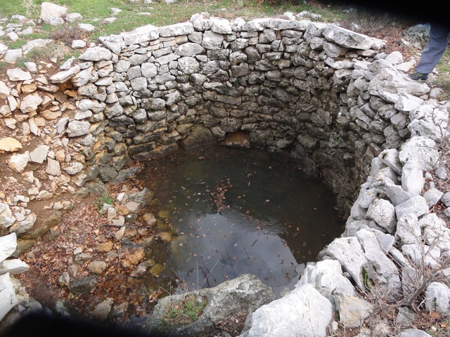
IMHO the problem is not so much the red clay, but the mixture with limestone gravel of inconsistent size. I am detecting on such terrain quite successfully, but only thank to the proportional audio and multiple passes over a same spot and different orientations can help me distinguish a buried boulder from it's red clay surroundings. To get a better picture of what I'm referring to, observe the collapsed left side of the well
Locals are cultivating this soil for ... I guess forever ... by separating stones from soil and making stone walls around their property. After few hundred generations they become neatly separated, soil and walls that is. Some of these walls go across whole islands, with no hint of their purpose or fate of their builders
The whole area is a bit wild-ish, and the weather is often extreme. This is a picture of a mild summer Bora in my mom's birth place, some 30km from Obrovac
No, the author's name is Gospić, nice coincidence. The photo is of Velebit Channel ... just for ambient. Can you imagine me sailing there at that weather? Well neither do I, but at few occasions I entered the harbour under sails with pretty much the same wind, only a bit less of the waves. It starts very quickly.
In summer there are also bush fires, so perhaps that may contribute to the viscosity of samples.
Here is a report with quite a bit of information on Croatian soils. The worst for viscosity is a "Terra Rossa" from Rugoznica with a lf - hf susceptibility difference of 49. See Annex B - Soil Measurement Data.
Here is a report with quite a bit of information on Croatian soils. The worst for viscosity is a "Terra Rossa" from Rugoznica with a lf - hf susceptibility difference of 49. See Annex B - Soil Measurement Data.
I don't get it. Now just about everybody knows that magnetite is the least offensive soil component and the viscous species are the worst. We know where the most viscous soil can be found. Why not simply design for the "worst case scenario" and be done with it?
 Tweet
Tweet


Comment