Announcement

Collapse
No announcement yet.

Simple Russian PI detector Pirat

Collapse
X
 
  • Filter
  • Time
  • Show
Clear All
new posts

  • Tinny hope.
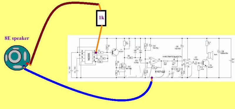
    Connect headphone (or small speaker, more Ohms - better) between pin 3 of NE555 and ground.
    If there is clear low tone in headphone, NE555 is OK.
    If NE555 is OK, then most probably your K157ud2 is kapput.

    Comment


    • Ok , i have measured everything right now, but not the IC's. Every resistor seems to be ok, elkos too, but one had 17uF instead of 10.
      Transistors tester says ok, PNP and NPN.

      Damn. i will test the NE555 Tomorrow. Can i use the 8 Ohm speaker for it? Or a piezo buzzer?

      This PI Detector was a cool thing.

      Comment


      • Originally posted by BKY1337 View Post

        Can i use the 8 Ohm speaker for it? Or a piezo buzzer?
        8E speaker will be OK (32 Ohms earphone even better).
        Solder two wire to it.
        One wire go to ground, another one use as probe tip (mean
        do not solder it to pin 3 - only touch for couple of seconds).
        It is better to check NE555 at base of T1, or solder 1k Ohm
        resistor in serial with your low Ohm speaker. In this case
        you can use free resistor pin as your probe tip.


        If you have piezo transducer (passive piezo element), you do not need serial resistor.
        Bigger diameter of piezo transducer will be better, due to better frequency response at
        low tone band.

        Comment


        • Thanks, for your work. I just saw that one resistor had 1 MegaOhm (measured at the pcb) but it was a 1k Ohm resistor , its the one right from the NE555.
          I will try to fix it tomorrow.

          Comment


          • Ok, i have tested it. Do you mean a steady tone? I can only get a short sound , its not oscillating , like the sound when you connect a speaker with a 3,5mm connector to something. Only for a part of a second when i connect it, and its silent after that.
            And i tested it at the other pins too after that and i can get the same sound at every pin. I think my 555 is damaged.

            I tested the N-Mosfet with multimeter and it works. Everything works.

            Comment


            • Yes, with resistor in series with speaker should be steady low tone at NE555 pin 3 (about 150Hz), not only short cracking in speaker, this is due battery.

              Comment


              • Thanks for the pictures. Perhaps it is this tansistor:

                Click image for larger version

Name:	transistor.jpg
Views:	1
Size:	51.3 KB
ID:	348519

                Also the electrolyte capacitors can get damaged if they have connection with wrong polarity.

                First I would clamp in a different 555 chip, next I'd change the transistor and elkos.
                If this doesn't helps you might be better off building a new circuit.

                Comment


                • I have already ordered some NE555. Do you mean this because theres is a white spot at the side of the transistor?
                  I have desoldered everything and tested with a transistor tester.

                  I need to look again what this white spot is.

                  Comment


                  • This is why it's best to build in discrete sections testing as you go. Power, Timing, Tx, , Coil, Rx, Signal Processing, Audio,

                    Comment


                    • Originally posted by BKY1337 View Post
                      I have already ordered some NE555. Do you mean this because theres is a white spot at the side of the transistor?
                      I have desoldered everything and tested with a transistor tester.

                      I need to look again what this white spot is.
                      Yes, the white change of black "plastic" -could have been caused by heat - or just is some light-reflection.

                      Depending on the material, you can see if something was burned using a magnificent-glass
                      or with macro-mode pictures. Sometimes there are even little blisters or "hills".

                      Faulty Elkos even can look like "blown up" or they have white-yellow dirt at the cap.
                      This happens especially if they get too much heat over longer time.

                      Another method is using the nose to find the burned spot - but the later the harder it works.
                      Holding the pcb directly at your nose while breathing in over the nose gently.
                      Perhaps you have still a small change to locate the burned part this way.

                      A fast method for checking resistors without desoldering them is clamping some
                      similar resistors parallel to the existing ones.

                      Diodes you can test directly with a voltmeter if they are burned or not.
                      Or with a simple battery - resistor - LED circuit.


                      Why don't you use this "good" opportunity and built or order some much better PI-circuit?
                      Or you built first a better one and if this one works you can still repair the old one.

                      Comment


                      • Thanks, i want to repair it because it was cool , i want to add the led mod to it too.
                        And i want to build the Pickini V4 as next project.

                        Comment


                        • I found this other: http://cxem.net/metal/Part6/6-20.php


                          It looks very simple and well functioning.


                          ...

                          Comment


                          • Think I'll give it a shot some day. No Actual Values given. Sad !
                            Simple metal detector on the principle of induction balance

                            I present you the scheme and design of a simple metal detector for making your own hands

                            Fig.1. Schematic diagram of a metal detector
                            The circuit is based on two NE555 chips. Here there is a transmitting (Tx) and receiver (Rx) coils, so the circuit can be conditionally divided into two parts. The left part is a rectangular pulse generator. The time-consuming components R1, R2, C1 are matched so that the output frequency is about 700 Hz. This is the frequency of the audible range. The pulses are transmitted through a current-limiting resistor R3.
                            Both coils are located in space in such a way that they together form a certain overlap zone and the system is in the induction balance. In this case, in the receiving coil, the zero voltage and the right-hand side of the circuit do not react at all. If a metal object appears nearby, an imbalance occurs and an audible signal appears.
                            The signal from the receiving coil is amplified by the transistor VT1 and goes to the input of the second IC. As the bipolar transistor VT1 KT3102EM is used, it can be replaced by any analogous one with a large gain factor. With the help of four resistors R5 - R8, a voltage divider is formed. Variable resistors serve to adjust the metal detector. R6 is a trimmer and is adjusted after the mutual placement of the coils. And R7 and R8 are for rough and fine tuning, they should be installed on the body of the device (ensure easy access to them).
                            The acoustic signal is created by the piezo radiator BA1, which can be taken from an unnecessary multimeter. But when testing the circuit, I liked the sound of a piezo-emitter with a built-in oscillator. Despite the fact that the pulse signal is formed at the output of DD2, it will not only signal well, but it will also allow to detect the slightest changes in sound when a metal object is detected.
                            Creating coils
                            To wind the coils of a metal detector, an enameled winding wire with a diameter of 0.3 mm is required. In my case, the maximum permissible diameter is 0.7 mm.
                            The optimum diameter of the winding of the coil is approximately 15-16 cm. You should pick up a round object (for example a bucket) to wind the coil around it. But you can use the device. To do this on a clean wooden surface you need to hammer nails in a previously drawn circle.

                            The inner diameter in my case is 15.5 cm. I wound 25 full turns. The number of turns can and even needs to be done more than me, for example, about 50 turns. The winding wire itself can be taken from unnecessary electric motors or power transformers.
                            When the coil is wound, carefully remove it from the device and wrap it with paper tape. In the end, you need to make two absolutely identical coils. Then use a knife to scrape off the varnish and after cleaning these ends need to be tinned.
                            Windings have the ability to bend and lose the correct geometry, so the coils need to be completely wrapped, for example with paper tape. After that, they need to be slightly flattened where they overlap each other. Often they are made similar to the letter "D" as shown in the figure below.

                            As a basis for search coils, it is convenient to use a sandwich panel, which is used for slopes of plastic windows.
                            The board will be some distance from the search coils and it is not recommended to use conventional wires. To connect the coils to the board, I used a shielded wire, if I'm not mistaken from the microphone.

                            Shielded wire for connecting the coils to the board.
                            The center wire should be soldered to the beginning of the coil, and the other to the negative supply as shown above.
                            For both coils, of course, the wires will be separate so that there is no interference.
                            Arrangement and tuning of coils
                            The system setup begins before the coils are glued to the base.
                            The trimmer resistor R6 is set to approximately 90 kΩ, and the adjusting resistors R7 and R8 are set to the middle position. Now you need to move the coils. The instrument will sound in two positions. With a wide and narrow overlap. I suggest locking the coils with their narrow overlap as shown in the figure below (position 2). According to my observations in position 2, sensitivity is better and more accurate positioning takes place.

                            After that, you need to glue it to the base properly. I did this with a hot glue. But if there is a desire, you can make deepenings for the coils at the bottom and fill them with epoxy.
                            Once the glue has solidified, you need to adjust the settings again. R7 and R8 we do not touch yet, they are installed in the middle position and the resistor R6 needs to achieve a position in which the sound emitter slightly crackles and so to say is in the boundary position between silence and squeaking (on the verge of failure). In the future, when using a metal detector, you only need to adjust the position of R7 and R8. This is due to the fact that the device is not ideal, the coils are not shielded, and the settings will deteriorate when the battery voltage is lost.
                            Option revision
                            If desired, you can make additional rework of the coils - shielding from external electromagnetic fields ("Faraday shield"). This is done after the initial coating of the windings, which was described earlier (paper tape or tape). Then you need to take long strips of aluminum foil and wrap the coils. This is not done completely, but a gap of about 1-2 cm is left at the place where the wires are output. The foil is connected to the end of the coil and connected to the minus supply. After that, the coil is covered with electrical tape.

                            I did not do this, because I was afraid of losing sensitivity.
                            Metal detector construction
                            After soldering the components, it is desirable to remove the residues of flux and rosin from the surface of the board. They can badly affect the operation of the circuit.
                            I decided to place the board in a metal box, and that there was no closure with soldered connections, the bottom of the case was covered with electrical tape. Later, I most likely pick up the plastic case.

                            Always pay attention to the stiffness of fixing the cables. It will be insulting if in the process of using anything discards.
                            The circuit will be powered by a battery of the "crown" type. The circuit has a low power consumption, but still it is better to put an alkaline battery, it will ensure the device works on several "cops".
                            The handle was made of a metal-plastic water pipe, and closer to the base, it was continued with plastic tubes, so that the coils did not react to the handle itself made of metal. The design was rather easy. The installation of shielded wires produced electrical tape. A box with a metal detector board was mounted higher, so that the adjusting resistor was at hand.
                            And here's another photo:


                            Tip
                            Every time before using the detector, you should use a variable resistor to achieve a rapid cracking of the radiator. The faster the crack, the more sensitivity.

                            The first find
                            Experiment: a coin with a diameter of 2.5 cm, I buried in the ground at a depth of 25 cm. When scanning, the coils were located at a distance of 5 cm from the ground. At the same time, the metal detector produced a distinct signal. I suppose that large metal objects will "ring up" deeper.
                            In any case, it takes me some time to get used to the metal detector and, after some searches, to sum up the final results of his abilities.
                            To this article there is a video, which shows the process of creating a metal detector and its test.

                            Comment


                            • Originally posted by homefire View Post
                              Think I'll give it a shot some day. No Actual Values given. Sad !
                              Simple metal detector on the principle of induction balance

                              I present you the scheme and design of a simple metal detector for making your own hands

                              Fig.1. Schematic diagram of a metal detector
                              The circuit is based on two NE555 chips. Here there is a transmitting (Tx) and receiver (Rx) coils, so the circuit can be conditionally divided into two parts. The left part is a rectangular pulse generator. The time-consuming components R1, R2, C1 are matched so that the output frequency is about 700 Hz. This is the frequency of the audible range. The pulses are transmitted through a current-limiting resistor R3.
                              Both coils are located in space in such a way that they together form a certain overlap zone and the system is in the induction balance. In this case, in the receiving coil, the zero voltage and the right-hand side of the circuit do not react at all. If a metal object appears nearby, an imbalance occurs and an audible signal appears.
                              The signal from the receiving coil is amplified by the transistor VT1 and goes to the input of the second IC. As the bipolar transistor VT1 KT3102EM is used, it can be replaced by any analogous one with a large gain factor. With the help of four resistors R5 - R8, a voltage divider is formed. Variable resistors serve to adjust the metal detector. R6 is a trimmer and is adjusted after the mutual placement of the coils. And R7 and R8 are for rough and fine tuning, they should be installed on the body of the device (ensure easy access to them).
                              The acoustic signal is created by the piezo radiator BA1, which can be taken from an unnecessary multimeter. But when testing the circuit, I liked the sound of a piezo-emitter with a built-in oscillator. Despite the fact that the pulse signal is formed at the output of DD2, it will not only signal well, but it will also allow to detect the slightest changes in sound when a metal object is detected.
                              Creating coils
                              To wind the coils of a metal detector, an enameled winding wire with a diameter of 0.3 mm is required. In my case, the maximum permissible diameter is 0.7 mm.
                              The optimum diameter of the winding of the coil is approximately 15-16 cm. You should pick up a round object (for example a bucket) to wind the coil around it. But you can use the device. To do this on a clean wooden surface you need to hammer nails in a previously drawn circle.

                              The inner diameter in my case is 15.5 cm. I wound 25 full turns. The number of turns can and even needs to be done more than me, for example, about 50 turns. The winding wire itself can be taken from unnecessary electric motors or power transformers.
                              When the coil is wound, carefully remove it from the device and wrap it with paper tape. In the end, you need to make two absolutely identical coils. Then use a knife to scrape off the varnish and after cleaning these ends need to be tinned.
                              Windings have the ability to bend and lose the correct geometry, so the coils need to be completely wrapped, for example with paper tape. After that, they need to be slightly flattened where they overlap each other. Often they are made similar to the letter "D" as shown in the figure below.

                              As a basis for search coils, it is convenient to use a sandwich panel, which is used for slopes of plastic windows.
                              The board will be some distance from the search coils and it is not recommended to use conventional wires. To connect the coils to the board, I used a shielded wire, if I'm not mistaken from the microphone.

                              Shielded wire for connecting the coils to the board.
                              The center wire should be soldered to the beginning of the coil, and the other to the negative supply as shown above.
                              For both coils, of course, the wires will be separate so that there is no interference.
                              Arrangement and tuning of coils
                              The system setup begins before the coils are glued to the base.
                              The trimmer resistor R6 is set to approximately 90 kΩ, and the adjusting resistors R7 and R8 are set to the middle position. Now you need to move the coils. The instrument will sound in two positions. With a wide and narrow overlap. I suggest locking the coils with their narrow overlap as shown in the figure below (position 2). According to my observations in position 2, sensitivity is better and more accurate positioning takes place.

                              After that, you need to glue it to the base properly. I did this with a hot glue. But if there is a desire, you can make deepenings for the coils at the bottom and fill them with epoxy.
                              Once the glue has solidified, you need to adjust the settings again. R7 and R8 we do not touch yet, they are installed in the middle position and the resistor R6 needs to achieve a position in which the sound emitter slightly crackles and so to say is in the boundary position between silence and squeaking (on the verge of failure). In the future, when using a metal detector, you only need to adjust the position of R7 and R8. This is due to the fact that the device is not ideal, the coils are not shielded, and the settings will deteriorate when the battery voltage is lost.
                              Option revision
                              If desired, you can make additional rework of the coils - shielding from external electromagnetic fields ("Faraday shield"). This is done after the initial coating of the windings, which was described earlier (paper tape or tape). Then you need to take long strips of aluminum foil and wrap the coils. This is not done completely, but a gap of about 1-2 cm is left at the place where the wires are output. The foil is connected to the end of the coil and connected to the minus supply. After that, the coil is covered with electrical tape.

                              I did not do this, because I was afraid of losing sensitivity.
                              Metal detector construction
                              After soldering the components, it is desirable to remove the residues of flux and rosin from the surface of the board. They can badly affect the operation of the circuit.
                              I decided to place the board in a metal box, and that there was no closure with soldered connections, the bottom of the case was covered with electrical tape. Later, I most likely pick up the plastic case.

                              Always pay attention to the stiffness of fixing the cables. It will be insulting if in the process of using anything discards.
                              The circuit will be powered by a battery of the "crown" type. The circuit has a low power consumption, but still it is better to put an alkaline battery, it will ensure the device works on several "cops".
                              The handle was made of a metal-plastic water pipe, and closer to the base, it was continued with plastic tubes, so that the coils did not react to the handle itself made of metal. The design was rather easy. The installation of shielded wires produced electrical tape. A box with a metal detector board was mounted higher, so that the adjusting resistor was at hand.
                              And here's another photo:


                              Tip
                              Every time before using the detector, you should use a variable resistor to achieve a rapid cracking of the radiator. The faster the crack, the more sensitivity.

                              The first find
                              Experiment: a coin with a diameter of 2.5 cm, I buried in the ground at a depth of 25 cm. When scanning, the coils were located at a distance of 5 cm from the ground. At the same time, the metal detector produced a distinct signal. I suppose that large metal objects will "ring up" deeper.
                              In any case, it takes me some time to get used to the metal detector and, after some searches, to sum up the final results of his abilities.
                              To this article there is a video, which shows the process of creating a metal detector and its test.
                              Missed it.

                              Designation
                              Programmable Timer and Oscillator NE555 2 Search in Fivel
                              Bipolar transistor KT3102EM BC538, BC548B, 1 Search in Fivel
                              Resistor 1 kΩ 1 Search in Fivel
                              Resistor 100 kΩ 1 Search in Fivel
                              Resistor 470 - 680 Ohm 1 Search in Fivel
                              Resistor 2 - 2.2 MΩ 1 Search in Fivel
                              Resistor 10 kOhm 1 Search in Fivel
                              Trimmer Resistor 100 kΩ 1 Search in Fivel
                              Variable resistor 100 - 500 kOhm 1 Coarse adjustment Search in Fivel
                              Variable resistor 15 - 20 kOhm 1 Fine Tuning Search in Fivel
                              Capacitor 0.01 uF 1 Search in Fivel
                              Capacitor 0.0027 uF 1 Search in Fivel
                              Electrolytic capacitor 100 uF 1 Search in Fivel
                              Electrolytic capacitor 100 - 470 μF 1 Search in Fivel
                              Piezo-emitter 1 Search in Fivel
                              Switch 1 Any Search in Fivel

                              Comment


                              • It looks very simple and well functioning
                                http://www.geotech1.com/cgi-bin/page...less/index.dat

                                matchless project

                                Comment

                                Working...